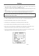
INSTRUCTIONAL MANUAL MOBILE GENERATORS SDG25S-6A7, SDG45S-6A6, SDG65S-6A6, SDG100S-6A6 MMD Equipment Inc. 121 High Hill Road Swedesboro, NJ 08085 Tel: (800) 433-1382 Fax: (856) 467-5235 www.mmdequipment.
Preface ◆ This manual explains and illustrates proper handling of the unit, method of daily inspection and maintenance to enhance the performance of AIRMAN’s generators. ◆ In order to use a machine safely, people with sufficient knowledge and sufficient technology need to deal with it. ◆ Before operating the unit, read the manual carefully, fully understand its operation and maintenance requirement. Maintain “SAFETY OPERATION AND PROPER MAINTENANCE OF THE UNIT”.
Table of Contents 1. Safety ....................................................................................................................................................... 1.1 Caution before Operation ................................................................................................................ 1.2 Caution during Operation ................................................................................................................ 1.3 Caution during Inspection and Maintenance .
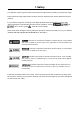
1.Safety This operation manual explains and illustrates general requirements for safety and cautions for safety. Please read these safety requirements carefully and fully understand the contents before starting the machine. For your better recognition, according to the degree of potential danger harmful to a human body, safety messages are classified into three hierarchical categories, namely, , , and with a caution symbol −attached to each message.
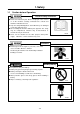
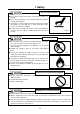
1.Safety 1.1 Caution before Operation Follow the safety instructions Read each instruction plate which is displayed in the manual or on the machine carefully, understand its content and follow the indications thereof. Keep the Safety Warning labels clean. When they are damaged or missing, apply new ones. Do not modify the machine without prior approval. The safety may be compromised, functions may be deteriorated, or machine life may be shortened.
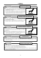
1.Safety Safety outfit When handling machine, do not wear; loose clothes clothes with unbuttoned sleeves hanging tie or scarf dangling jewelry Such outfit could be caught in the machine or dragged in the rotating portion of the machine, and could cause a serious injury. TR0084 Maintain both physical and mental health Do not operate the machine when you are tired or drunk or under the influence of drugs. Otherwise, a hasty conclusion or careless handling may cause unexpected injury or accident.
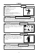
1.Safety 1.2 Caution during Operation Never touch the output terminals and interior of control board Never touch the output terminals during operation. Notice that the voltage of several hundreds volt is applied to the output terminal. When removing or connecting a connecting cable for changing load, be sure to switch OFF the circuit breaker, remove the starter key from the starter switch, then carry out a work. The operator must keep the key during operation.
1.Safety Do not touch hot parts Never work nearby hot portions of the machine while it is running. Do not touch hot portions of the machine while inspecting the machine when running. Such parts as engine, exhaust manifold, exhaust pipe, muffler, and radiator are especially hot, so never touch those parts, because it could cause scalding. Coolant water and engine oil are also very hot and dangerous to touch. Avoid checking or refilling them while the unit is running.
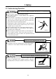
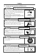
1.Safety 1.3 Cautions during Inspection and Maintenance Hang a “Now Checking and under Maintenance” tag Before starting inspection, switch off the circuit breaker of this machine, remove the starter key from the starter switch, and then hang a “Now Checking and under Maintenance” tag where it can be easily seen. The checker must keep the key during checking and maintenance. Remove the negative (–) side cable from the battery.
1.Safety Taking off the radiator cap Be sure to stop the machine first and then loosen the radiator cap slowly, after the coolant water is sufficiently cooled and the inner pressure is released. If this procedure is neglected, its inner pressure can blow off the cap,and steam jetting out of the radiator could result in causing scalding. Follow these procedures under all circumstances.
1.Safety 1.4 Safety Warning Labels Following labels are attached to the machine. Keep them clean at all times. If they are damaged or missing, immediately place an order with your nearest dealer for replacement. Part numbers are indicated on the lower right corner of the label. Adhere a new one to the original location.
1.Safety ● The pasting position of safe warning label is as follows.
1.
2. Part Names 2.2 Internal Components SDG25S-6A7 1 2 3 4 5 6 13 12 11 10 9 8 1. Control panel 8. Battery 2. Engine 9. Engine oil level gauge 3. Air filter 10. Sedimentor 4. Engine oil filler port 11. Fuel filter 5. Reserve tank 12. Generator 6. Radiator 13. Output terminals 7.
2. Part Names SDG65S-6A6 1 2 15 14 3 13 4 12 11 5 6 7 8 10 9 A040576 1. Control panel 9. Fuel tank 2. Air filter 10. Engine oil filler port 3. Engine oil level gauge 11. Fuel air-bleeding electromagnetic pump 4. Reserve tank 12. Engine oil filter 5. Engine 13. Battery ※ 6. Sedimentor 14. Output terminals 7. Fuel filter 15. Generator 8. Radiator Instrument 12 marked “ ※ ” are provided on the other side (opposite side of maintenance).
3. Installation 3.1 Transporting Unit Transportation Use the lifting bail“1”at the center of bonnet for hoisting up and down the machine. Since the rope hook is not strong enough to be used for hoisting, never use it to prevent falling accident. When transporting the machine, be sure to put it on the truck bed and use the rope hooks to secure it with rope Do not hoist up the machine while it is running. Otherwise, a fatal trouble or serious accident may occur. 3.1.
3. Installation 3.3 Selecting Cable Select a cable with sufficient diameter by considering the permissible current on the cable and the distance from the generator to the load. If the current flowing to the load exceeds the permissible current of the cable, resultant overheating may burn the cable. Similarly, if the cable is too small in thickness to the length, the input voltage to the load will fall to cause the load input power to drop, as a result, the performance of the machine cannot be displayed.
3. Installation 3.4.3 The Maximum Combined Simultaneous Power Consumption Never exceed the maximum combined simultaneous power consumption. The following chart shows the maximum power available from the 120V-20A GFCI receptacles during simultaneous consumption (main terminals and receptacles) for both single or three phase settings.
4. Operation 4.2.4 GFCI (Ground-fault circuit interrupter) Receptacles Using the generator in rain, snow or near water can lead to death from electric shock. Keep the generator dry. All of the 20 ampere 120 volt receptacles on the generator are protected by a GFCI (Ground-fault circuit interrupter) for protection against the hazards of ground fault currents.
4. Operation Grounding method Machine grounding terminal Load equipment Grounding rod Grounding rod A040174-1 4.2.5 Circuit protector (CP) for AVR protection AVR is equipped with circuit-protector (CP) for protection against overcurrent. Under the following cases, it happens to function. In case the machine gets overloaded while engine speed is still lower. In case the output voltage of generator is increased higher than the specified voltage.
4. Operation 4.3 Check before Starting the Unit Check before starting the unit Be sure to check the unit before operation. When any abnormality is found, be sure to repair it before starting the unit. Be sure to make daily check before operation. If the unit is operated without prior check and without noticing its abnormality, such operation could cause seizure of components or may even cause fire. 4.3.1 Check Engine Oil Level Unit should be on level before checking oil level.
4. Operation 4.3.3 Check Fuel Level Fire prevention Do not, under any circumstance, bring lit cigarettes and/or matches to the fuel. The fuel is extremely flammable and dangerous. Be careful of fire because it is very likely to catch fire. Refuel only after stopping the engine, and never leave open fuel can near the machine. Do not spill. It could cause a fire. When it is spilt, wipe it up completely. Refilling fuel tank should be done in an outdoor well-ventilated place.
4. Operation 4.4 Unit Operation Keep the door shut and locked when machine is in operation. If opening the door is necessary, be careful not to touch rotating or hot parts. Burns or serious injury could result. After the engine starts up, warm up it under unload for approx. five minutes. Warming up after starting up is necessary for smooth operation of the engine. Do not operate the engine at full load immediately after it starts up. This will shorten the equipment life.
4. Operation This machine is so designed for safety that operator may not touch the output terminal during operation. If you open the output terminal cover during operation with three-phase breaker switched “ON” , the three-phase breaker will be “OFF” to cut power supply to the output terminal. When starting operation , make sure that the output terminal cover is closed. 4.4.2 Meter and Indicator Lights while Operating During normal operation, each indication of instruments is shown in the table below.
5. Periodic Inspection/Maintenance 5.1 Important Items at Periodic Inspection and Maintenance or after Maintenance The manual shows proper interval for periodic inspection and maintenance under normally operating conditions. Inspection and maintenance should be performed more often under extremely harsh conditions.
5. Periodic Inspection/Maintenance 5.2 Daily Inspection and Keeping Operation Log Be sure to carry out daily inspection every morning before operation. See Chapter 4 “OPERATION” of the manual for the details of inspection. Pay attention to and carefully observe the following points during daily operation or inspection and maintenance work. If any trouble or abnormality is found, immediately investigate its cause and make repairs.
5. Periodic Inspection/Maintenance 5.3 Periodic Inspection List Such items marked ○ shall be carried out by customers. For the following items or clauses marked ●, contact us directly or our distributors because they require expert technical knowledge on them. ◎Refer to engine operation manual for inspection and maintenance of an engine. (Unit : Hour) Maintenance Generator Check each instrument and warning lamp. Daily 50 250 500 Page Check insulation resistance. Check GFCI receptacles.
5. Periodic Inspection/Maintenance 5.4 Periodic Replacement of Parts Use our genuine elements Air filter is a crucial component for the performance and the life of a unit. Use genuine part for replacement. Part number changes upon modification. For replacement of parts, make sure whether the part number is correct or applicable.
5. Periodic Inspection/Maintenance 5.5 Maintenance 5.5.1 Change Engine Oil At 50 hours for the first change and every 500 hours thereafter Caution in filling or draining engine oil When checking, replenishing, and draining the engine oil, be sure to wait 10 to 20 minutes after engine stops until it cools down. Engine oil is very hot and highly pressurized during or just after the operation. Hot oil could blow out and can cause injury.
5. Periodic Inspection/Maintenance 5.5.11 Clean outside of Radiator and Intercooler (Intercooler: SDG100S only) Every 500 hours When the fin tubes“3”of radiator“1”and inter cooler“2” are clogged by dust or other foreign materials, the heat exchange efficiency drops and this will raise coolant temperature. These tubes and fins should be cleaned depending on the state of dirt inside the tubes even before maintenance schedule.
5. Periodic Inspection/Maintenance 5.5.13 Change Coolant 1,000 hours or every 2 years Taking off radiator cap Be sure to stop the machine and loosen the radiator cap slowly, after the coolant water is sufficiently cooled and the inner pressure is released, then take the cap off. If this procedure is neglected, the inner pressure can blow off the cap. Steam jetting out of the radiator could result in causing scalding. Follow the procedure under all circumstances.
6. Maintenance/Adjustment 6.1 Maintenance of Battery Handling battery Keep flames away from battery. Battery may generate hydrogen gas and may explode. Therefore, recharging should be done at a well-ventilated place. Do not spark near the battery nor light a match, nor bring lit cigarette and match close to the battery. Do not check the battery by short-circuiting the positive and negative terminals with a metallic piece.
6. Maintenance/Adjustment 6.2 Troubleshooting Should any trouble occur during operation, do not leave it. Investigate the cause and take appropriate measures. Read the manual carefully and fully understand what to do in case of trouble. The better you understand the construction and function of the unit, the faster you can find a problem and solution. This chapter describes the state, cause and countermeasures of important troubles in detail: Symptom Cause Counter measures Starter does not rotate.
6. Maintenance/Adjustment Symptom Even when operated at a rated speed, no voltage or too low voltage generated. (1) (2) (3) (4) (5) (6) (7) (8) (9) Too high voltage generated when set at the rated frequency (50Hz/60Hz), Voltage will not drop even when the voltage regulator controlling knob is turned.
7. Storage of the Unit 7.1 Preparation for Long-term Storage When the unit is to be kept unused in storage for a long time, be sure to follow the preparations below and put the unit in a dry and less dusty place. Put the unit in a temporary cabin if it is stored outside. Avoid leaving the unit outside with a sheet cover directly on the paint for a long time, or this will cause rust to the unit. Perform the following treatments at least once every three months.
8. Specifications 8.1 Specifications Model SDG25S-6A7 Brushless system Exciting system Armature connection Star with Neutral ZigZag Three Single 80 100 Generator Phase Power factor % Frequency Hz 60 Rated output kVA 25 14.4 Rated output kW 20 14.
8.
8. Specifications Model SDG65S-6A6 Brushless system Exciting system Armature connection Star with Neutral ZigZag Three Single 80 100 Generator Phase Power factor % Frequency Hz 60 Rated output kVA 63 36.5 Rated output kW 50 36.
8.
8. Specifications 8.
9. Wiring Diagram 9.1 Generator Wiring Diagram SDG25S-6A7 Terminal plate Voltage selector sw. To Battery A.C.
9. Wiring Diagram SDG45S-6A6,65S-6A6 Terminal plate Voltage selector sw. To Battery A.C.
9. Wiring Diagram SDG100S-6A6 Terminal plate To Battery A.C.
9. Wiring Diagram 9.
9.
9.
9.