C4D-4MUSAD_V6 - USER GUIDE 17/05/2019
Table of contents Preface..................................................................................................................................... 3 Warnings and notices .......................................................................................................... 3 FCC Regulations .................................................................................................................... 3 FCC RF Exposure Information (SAR) ....................................................
Preface The information contained in this installation guide is subject to changes in order to improve the reliability, design or features without prior notice. Mobile Devices Ingénierie reserves the right to make changes in the content without obligation to notify any person or organisation of such changes or improvements.
FCC RF Exposure Information This device is designed and manufactured not to exceed the emission limits for exposure to radio frequency (RF) energy set by the Federal Communications Commission of the United States. In order to avoid the possibility of exceeding the FCC radio frequency exposure limits, human proximity to the antenna shall not be less than 20 cm (8 inches) during normal operation.
1. Hardware features OBD Dongle Performance Power supply Processor RAM NAND Flash External power supply range External voltage measurement Li-pol battery Modem Cortex A5 - 500MHz 128 Mbytes 256 Mbytes 8-18V ● 450mA.h 4G Cat-M1 data module (SARA R410M-52B) Modem antenna Internal Positioning GNSS receiver U-blox M8 (GPS, GLONASS, BeiDou) GNSS antenna Internal Interface & Telematics USB (2.
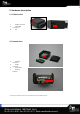
2. Hardware description 2.1. External view 2 1. 2. 3. 1 ODB connector microUSB connector LED 3 2 2.2. Internal view 4 7 6 4. Modem antenna 5. GNSS antenna 6. SIM holder 7.
2.
3. Preparing/installing the device 3.1.
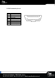
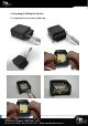
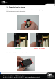
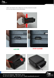
3.2. Properly close the device First, check that the hole of the electronic card is correctly inserted in the plastic part. If it’s not inserted proceed as shown below. GOOD Second, insert the GPS antenna as shown below.
Third, check that the micro USB port is correctly inserted on its place. If it’s not inserted proceed as shown below. GOOD Finally, insert the battery and place the screw.
3.3. Install the OBD Dongle Connect the OBD Dongle on your vehicle OBD connector. Note : The USB port is not intended to be used during driving operation. The USB is only used for flashing and debug purpose via USB key or computer. 4. LED sequences The Dongle has a two-coloured LED, green and red. When both colours are brightened, you can see an orange light.