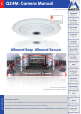
EN Q24M: Camera Manual The HiRes Video Company Allround Easy. Allround Secure. High-resolution 180° Panorama High-resolution 180° Panorama www.mobotix.com Version 09/06/Latest PDF file: www.mobotix.com > Support > Manuals HiRes Video Innovations The German company MOBOTIX AG is known as the leading pioneer in network camera technology and its decentralized concept has made high-resolution video systems cost efficient.
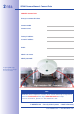
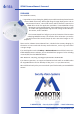
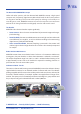
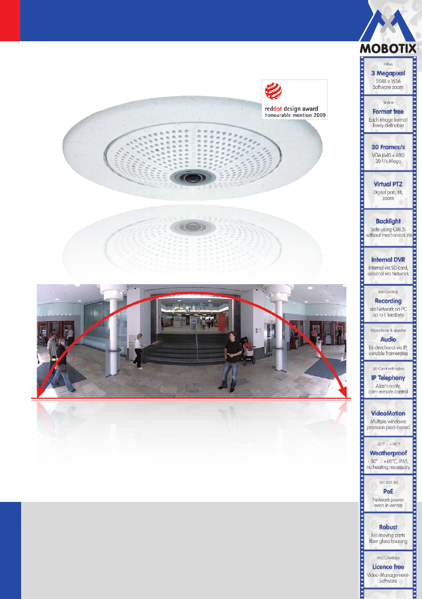
/��� 156 Q24M Camera Manual: Camera Data MOBOTIX Camera Data Enter your camera data here. Camera model: Camera name: Factory IP address: Current IP address: DHCP: Admin user name: Admin password: Original Q24M image; Wall mounted at a height of 2.3 m in a bank High-resolution 180° Panorama Note MOBOTIX offers inexpensive seminars which include workshops and practical exercises: Basic Seminar three days, Advanced Seminar two days. For more information, please visit www.mobotix.
/��� 156 Contents Foreword 6 The MOBOTIX Concept 8 Innovative Hemispheric Technology 10 MOBOTIX Hemispheric Technology 12 Superior Storage Solution 14 Added Security Value 16 Cost Benefits And Technical Advantages 18 1 INTRODUCTION 20 1.1 Q24M Overview 20 1.2 Q24M: Next Generation Hemispheric Technology 29 1.3 General MOBOTIX Camera Functions 30 1.4 Lens Options, Hardware And Software Features 36 2 INSTALLATION 40 2.1 Preparing The Installation 40 2.1.1 2.1.2 2.1.3 2.
/��� 156 Q24M Camera Manual: Contents 2.6 Mounting The Camera With The In-Ceiling Set 72 2.6.1 Mounting Instructions 2.6.2 In-Ceiling Set 2.6.3 Procedure 72 73 76 2.7 78 Installing The Vandalism Set 2.7.1 Mounting Instructions 2.7.2 Vandalism Set 2.7.3 Procedure 78 79 82 2.8 84 Installing The Wall Mount 2.8.1 Mounting Instructions 2.8.2 Wall Mount 2.8.3 Procedure 84 85 88 2.9 Installing The Corner And Pole Mount 90 2.9.1 2.9.2 2.9.3 2.9.4 2.9.
/��� 156 3.3 Virtual PTZ And Special Q24M Configuration 122 3.3.1 Preparing The Virtual PTZ Function 3.3.2 Special Q24M Configuration In The Browser 3.3.3 Overview Of The Available Camera Views 122 124 130 3.4 MicroSD Card Recording 134 3.4.1 3.4.2 3.4.3 3.4.4 3.4.5 3.4.6 3.4.
/��� 156 Q24M Camera Manual: Foreword Foreword Dear MOBOTIX customer, Congratulations on purchasing this globally unique and discreet hemispherical network camera "Made in Germany". With its wide range of image display options such as the panorama function, a virtual PTZ function and live distortion correction, the Q24M offers whole new application possibilities.
7/��� 156 Q24M with 10° On-Wall Set Q24M in the In-Ceiling Set © MOBOTIX AG • Security-Vision-Systems • Made in Germany www.mobotix.com • sales@mobotix.
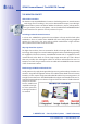
/��� 156 Q24M Camera Manual: The MOBOTIX Concept The MOBOTIX Concept HiRes Video Innovations The German company MOBOTIX AG is known as the leading pioneer in network camera technology since its founding in 1999, and its decentralized concept, has made highresolution video systems cost efficient. Whether in embassies, airports, railway stations, ports, gas stations, hotels or on highways - over one hundred thousand MOBOTIX video systems have been in operation on every continent for years.
/��� 156 The Decentralized MOBOTIX Concept Unlike with other systems, with the decentralized MOBOTIX concept a high-speed computer and, if requested, digital memory (MicroSD/SD card) is built into every camera for long-term recording. The PC now serves purely for viewing, not for analysis or recording. As a result, MOBOTIX cameras can record in response to an event even without the PC being switched on and digitally store the videos with sound.
/��� 156 Q24M Camera Manual: Innovative Hemispheric Technology INNOVATIVE HEMISPHERIC TECHNOLOGY The Hemispheric Camera The primary components of the hemispheric camera include a fisheye lens, a high-resolution image sensor and image correction software that is integrated into the camera. Using an ultra-wide angle fisheye lens, the camera captures a 180° hemispheric image of the room and projects it onto a high-resolution image sensor.
/��� 156 Less Cameras Thanks To Panoramic Views The perspective of the hemispheric image can also be transformed into an ultra-wide angle panoramic view spanning 180° if the camera is mounted on a wall, providing a wall-to-wall view of the room without any blind spots. It offers a substantially better view of the scene, compared to other cameras, it also results in the need for fewer cameras overall. When ceiling mounted, one camera can also capture an entire room by two opposite panoramic views.
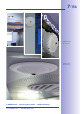
/��� 156 Q24M Camera Manual: MOBOTIX Hemispheric Technology MOBOTIX HEMISPHERIC TECHNOLOGY Perfect Room Overview ith in-ceiling moun Q24M w t With the innovative MOBOTIX Hemispheric Technology, an entire room can be ideally monitored. or instance, one single, particularly elegant and discreet, Q24M replaces the time-consuming and expensive installation of several standard cameras.
/��� 156 One Camera, More Views The surround function of the Q24M (ceiling mounted) immediately replaces four conventional cameras and shows four different directions simultaneously in quad view on a monitor. Virtual PTZ is available for each of the four views. Together with the 180° panorama the Q24M can deliver two more views simultaneously, making it possible to see the overview and to focus on two scenes at the same time (Display Mode “Panorama Focus“).
/��� 156 Q24M Camera Manual: Superior Storage Solution Superior Storage Solution The Market Demands Better Image Quality When it comes to future-proof video surveillance systems, it is not a matter of analog or digital but whether it is high-resolution or not. It is important to note that HiRes video only with decentralized network camera technology can be implemented at much lower cost than any other type of video surveillance system.
/��� 156 Flash memory is a sophisticated form of semiconductor memory without mechanical moving parts and represents the storage medium of the future thanks to its reliability, ease of use and low cost.
/��� 156 Q24M Camera Manual: Added Security Value Added SECURITY VALUE Q24M Panorama: one camera - three simultaneous views high-resolution 180° Panorama Robust, Low-Maintenance Technology The real added value of MOBOTIX products is reflected in characteristics such as enhanced functionality, long life and robustness. MOBOTIX cameras basically have no moving parts. This makes the cameras very resistant to wear and tear, and reduces both maintenance costs and power consumption.
17/��� 156 Sound Increases The Chance Of Detection In the event of an alarm, MOBOTIX cameras can turn on their built-in microphones and record lip-synchronous sound. They are therefore an even greater help in analyzing a situation and easing clarification. In addition, the video system can be used for bidirectional communication via a loudspeaker/microphone. No Problems With Backlight MOBOTIX cameras are not affected adversely by sunlight such as direct sunlight.
/��� 156 Q24M Camera Manual: Cost Benefits And Technical Advantages The Most Important Cost Benefits 1 2 3 4 5 6 7 8 9 Increased resolution reduces amount of cameras needed 1536-line, high-resolution sensors give a better overview and allow monitoring an entire room with just one camera from the corner Reduced installation costs at any distance Standard Ethernet connection enables the use of use of common network components such as fiber, copper and wireless (WLAN) IIntelligent recording technology r
/��� 156 The Most Important Technical Advantages Progressive-scan instead of half-frame blur Megapixel sensor and image processing inside camera with digital white balance generates sharp and true color images at every scale Sun and backlight compensation CMOS-sensor without auto iris, digital contrast enhancement and configurable exposure measurement zones guarantee optimal exposure control Dual camera technology: 2-in-1 Two possible camera views with picture-in-picture technology or 180° panoramic
/��� 156 Q24M Camera Manual: INTRODUCTION 1 INTRODUCTION 1.1 Q24M Overview Q24M with in-ceiling mount Innovative Hemispherical Technology For The Perfect Room Overview The MOBOTIX Q24M Hemispheric camera is an elegant, ultra-compact and weather proof IP network dome camera with a special hemispheric lens (fisheye). When mounted on the ceiling, the camera is capable of providing full 360° allround view or a 180° panorama when mounted on a wall.
/��� 156 Q24M Overview Panorama Focus – One Camera, Three Views (Wall-Mounted) Maximum room overview while simultaneously viewing detail in a single image: the Q24M is capable of providing two more views at the same time with the 180° panorama, allowing you to focus on two scenes in parallel ("Panorama Focus" display mode).
/��� 156 Q24M Camera Manual: INTRODUCTION Full Image And Normal View With innovative MOBOTIX Hemispheric Technology, an entire room can be ideally monitored. For instance, one single, particularly elegant and discreet, Q24M replaces the time-consuming and expensive installation of several standard cameras.
/��� 156 Q24M Overview Surround View (Quad View), Based On The Correct Full Image The Q24 “Surround” display mode replaces (when ceiling mounted) four cameras, and shows four directions simultaneously on the monitor in a quad view. The preset North position can be moved to any direction in the image; the camera generates the other three directions (East, South, West) automatically and stores them as separate views.
/��� 156 Q24M Camera Manual: INTRODUCTION Virtual PTZ (vPTZ) – No Motor Required The Q24M can zoom in on detail as well. These vPTZ functions are a standard feature in the integrated Q24M camera software. The image from the hemispheric camera can be enlarged using e.g. the mouse wheel, a joystick or a software-controlled PTZ panel, and you can "move" the view to any section of the image. This provides the features of a mechanical PTZ camera without the disadvantages of maintenance and wear.
/��� 156 Q24M Overview Simultaneous Corrected Live Image And Full Image Recording All conventional, motorized PTZ cameras only store the image that is currently viewed as the live image (live image recording). This has one serious disadvantage as the recording can only show what has happened in the "visible" portion of the image; the rest is lost and cannot be examined later on. For this reason, MOBOTIX has added the new full image recording feature to the Q24M.
/��� 156 Q24M Camera Manual: INTRODUCTION Maximum Ease Of Use The camera software is responsible for image correction, reducing load on the user PC The full image generated by the hemispherical lens (fisheye) can be difficult to evaluate. MOBOTIX solves this problem with image distortion correction in the camera software that displays perfectly corrected live images.
Q24M Overview 27/��� 156 Internal DVR The Q24M SECURE model features direct recording to integrated MicroSD cards, which makes the camera fully independent of any external storage media, even for longer periods of time. The camera internally saves high-resolution video and audio, without requiring an external storage device or PC or overloading the network whatsoever. Old recordings may be overwritten automatically or deleted automatically after a specified period of time.
/��� 156 Q24M Camera Manual: INTRODUCTION The integrated DVR functionality with long-term storage on a MicroSD card also makes the camera an ideal solution for mobile applications since it only requires a power supply via the network cable (standard PoE) for full event-driven recording with video and audio, thus delivering a complete standalone product. Application examples in this context are installations in public transportation such as busses, trains, aboard ships, airplanes, etc.
Q24M: Next Generation Hemispheric Technology 1.2 Q24M: Next Generation Hemispheric Technology The Q24M Hemispheric camera is the more powerful and optimized successor to the Q22M and is delivered with a recording capacity of 4 GB integrated as standard. The Q24M has a new microprocessor and a modified system platform. The result is more than twice the processing power, which enables smooth video frames rates, even in the high-resolution 180° panoramic view.
/��� 156 Q24M Camera Manual: INTRODUCTION 1.3 General MOBOTIX Camera Functions Like all other MOBOTIX cameras, the Q24M models include a range of (software) functions, such as video motion detection, long-term recording, alarm messaging and video IP telephony, to name but a few. Unlike in camera systems from other manufacturers, buying and installing additional software on the computer is unnecessary.
/��� 156 General MOBOTIX Camera Functions mobile or via Internet telephony is just as easy as event-controlled voice messages directly from the camera. Internet Telephony (SIP) And Video SIP Video SIP allows establishing audio/video connections to the camera using Windows Messenger or similar applications (e.g. CounterPath X-Lite/ Eyebeam). This feature also allows the camera to be remote controlled using the phone keys, the camera itself can place phone calls in case of alarms.
/��� 156 Q24M Camera Manual: INTRODUCTION recording, upload images to a web site or send e-mails with video/audio clips. Vacation times and holidays can be programmed. Remote Alerting In case of an alarm, MOBOTIX cameras automatically pop up windows or activate other functions at a remote security control center. The cameras can use network/wireless, GSM/GPRS/UMTS (3G) or Internet connections for this purpose.
General MOBOTIX Camera Functions 33/��� 156 30 Cameras Live Using MxControlCenter Instead of using a web browser, you can also download the free-of-charge MxControlCenter from www.mobotix.com, which allows fast display of up to 30 MOBOTIX cameras on one monitor. In addition, MxControlCenter can process incoming alarms with sound from the cameras and allows comfortable search and evaluation of alarm video clips (including audio).
/��� 156 Q24M Camera Manual: INTRODUCTION All settings selected in MxEasy (e.g. virtual camera position, zoom, brightness, volume, microphone sensitivity, image storage, signal outputs) are usable immediately and are stored instantly in the configuration of the corresponding camera. The calendar function integrated in the Alarm Planner provides access to innovative features for scheduled settings of one or more cameras.
General MOBOTIX Camera Functions • Time Tables with handling of customized holidays and vacations. The time tables are used to control the camera's arming, image recording messaging, logos, the obscure image function as well as other features. • Remote signaling for master/slave cameras, with the master camera controlling the arming status of the slave cameras. This allows arming, for example, of all slave cameras using a key switch connected to the master camera.
/��� 156 Q24M Camera Manual: INTRODUCTION 1.4 Lens Options, Hardware And Software Features MOBOTIX Q24M cameras come with a standard L11 fisheye lens with a 180° horizontal image angle. The camera is also available with an L22 Super Wide-Angle lens with a horizontal image angle of 90°. The integrated virtual PTZ features of the camera software or MxControlCenter/MxEasy properly correct the lens distortion that is specific to each of the lenses.
/��� 156 Lens Options, Hardware And Software Features Lens Table L11 L22 35mm equivalent focal length 11 mm (0.43 in) 22 mm (0.87 in) Actual focal length 1,8 mm (0.07 in) 4 mm (0.16 in) Aperture 2.0 2.0 Original image Horizontal image angle 180° 90° Vertical image angle 160° 67° Distance 1 m (1.09 yd): m m Image width infinite 2.0 Image height 11 1.3 Distance 3 m (3.28 yd): m m Image width infinite 10.0 Image height 55 6.6 Distance 10 m (10.
Q24M-Secure D22 MX-Q24M-Sec-D22 Q24M-Secure D11 MX-Q24M-Sec-D11 Q24Mi-Basic D22 MX-Q24Mi-Basic-D22 Q24M Camera Manual: INTRODUCTION Q24Mi-Basic D11 MX-Q24Mi-Basic-D11 38/��� 156 Q24M Hardware Features *Special MiniUSB adaptor cable available as an accessory Outdoor weatherproof Ethernet/ISDN/USB/RS232 MicroSD slots Integrated microphone/speaker Mono (M) / Dual (D) Image Sensor Lens IP54 IP65 IP65 E /- / - /- E /- / U*/- E /- / U*/- - - 1 1 -/X -/X X/X X/X M M M M Color Color Colo
/��� 156 Lens Options, Hardware And Software Features The Web version is only available for the M12 M12 Secure Model IT Model Q24M Web Model D22M M22M Basic Model D12 The Basic version is only available for the D22M and Q24M The IT version is not available for the Q24M Software Features (All Models) Digital zoom (continuous) with panning Motion JPEG/MxPEG video streaming X* X X X X/X X/X X/X X/X Custom exposure windows X X X X Video Motion detection X X X X Time and event co
/��� 156 Q24M Camera Manual: INSTALLATION 2 INSTALLATION The Q24M is primarily designed for installation on walls or ceilings. The supplied L11 180° lens captures the entire room, practically from wall to wall and from floor to the ceiling. See sections 2.4 and above. for the different installation options; drilling templates can be found at the end of the manual. 2.1 Preparing The Installation Before mounting the MOBOTIX Q24M, the following questions should be answered: 1.
/��� 156 Preparing The Installation 2.1.1 Wall-Mounted To make optimal use of the high-resolution 180° panorama functionality of the Q24M, the camera must be mounted on an internal or external wall. The entire hemisphere of the room directly in front of the camera is then effectively monitored, from the wall on the left of the camera to the wall on the right.
/��� 156 Q24M Camera Manual: INSTALLATION Selecting An Appropriate Camera Position The Q24M is primarily suited to providing an excellent overview, and less suitable for more exact details. For active operation, the camera should be mounted at a (out of direct reach) height ranging from 2.5 to 3.5 m. People, for example, may be identified very well at distances of up to 1.5 m, and with sufficient detail at up to 3 m. Objects can be recognized even at distances of 5 m and more from the camera.
/��� 156 Preparing The Installation Wall Installation With The 10° On-Wall Set For Image Optimization An on-wall set, available as an accessory in 0° and 10° inclinations, may also be used for installation. While the 0° set primarily offers easier installation and more storage space for cables and add-on modules (WLAN, connectors, etc.), the 10° set may also increase the image quality in certain cases.
/��� 156 Q24M Camera Manual: INSTALLATION 2.1.2 Ceiling-Mounted Discreet ceiling installation using the In-Ceiling Set Thanks to its hemispherical lens, a single Q24M can monitor an entire room right into each of the four corners (360° Panorama View). The camera's should ideally be positioned on the ceiling in the center of the room. Due to its inherent physical and optical properties, the precision of the lens decreases as the distance from the lens grows.
Preparing The Installation 45/��� 156 Non-Square Rooms When viewing a 360° (full) image in the browser, you will notice that the top and bottom of the image is not fully visible, i.e. some image information has been clipped. This is not a fault of the camera, but intended behavior that aims at achieving the best possible utilization of the image sensor by the camera software.
/��� 156 The camera should not be directly mounted to metal surfaces (condensation may damage the camera): in such cases, MOBOTIX recommends using the On-Wall Set or Wall Mount Wall Mount (MX-OPT-WH) On-Wall Set (MX-OPT-AP) Q24M Camera Manual: INSTALLATION Lowered Mounting Or Mounting on Extensions When mounting the camera in rooms with a high ceiling, or outdoors, it is sometimes advisable to mount the camera in a lower position.
Preparing The Installation 47/��� 156 2.1.3 Mounting Options On-Wall Installation (MX-OPT-AP) The On-Wall Set can reliably protect external cables if the cables cannot be fed in the center below the camera housing. The On-Wall mount also provides ample space for extra modules. On-Wall Set (IP65, for outdoor applications) On-Wall Installation With 10° Inclination (MX-OPT-AP-10DEG) This On-Wall Set is identical to the regular On-Wall Set, except that the mounted camera is tilted by 10 degrees.
/��� 156 Q24M Camera Manual: INSTALLATION 2.1.4 Network Connection And Power Supply, UPS Power over Ethernet (PoE Conforming To IEEE 802.3af) The Q24M supports the Power over Ethernet standard IEEE 802.3af (PoE) All Q24M models are supplied with power using the PoE standard. The Network Power Adapter (MX-NPA-PoE-Set) may be used for smaller installations. For larger installations, it is worth investing in a PoE capable supply device available on the market.
Preparing The Installation 49/��� 156 Using Uninterruptible Power Supplies (UPS) In order to maintain a continuous power supply even when utility power fails, you should install an uninterruptible power supply (UPS). These devices also provide full protection against electrical surges and voltage fluctuations and thus enhance the reliability of the system as a whole. When using a more powerful 19" rack-mounted UPS, you can also protect all other network components (e.g.
/��� 156 Q24M Camera Manual: INSTALLATION 2.1.6 Wiring, Fire Prevention, Lightning And Surge Protection When installing the wiring inside or outside of buildings, make sure you always adhere to the relevant regulations on wiring, fire prevention and protection against lightning.: MOBOTIX cameras are protected against the effects of small electrical surges by a range of measures. These measures, however, cannot prevent the camera from being damaged when stronger electrical surges occur.
Preparing The Installation Lightning And Surge Protection More information is available at an institution such as the International Electrotechnical Commission (IEC, www.iec.ch) or at a manufacturer of protection devices against lightning and electrical surges, such as Dehn (www.dehn.de). © MOBOTIX AG • Security-Vision-Systems • Made in Germany www.mobotix.com • sales@mobotix.
/��� 156 Q24M Camera Manual: INSTALLATION 2.2 Q24M Basic/Secure: Delivered Parts, Components, Dimensions 2.2.1 Delivered Parts And Camera Components *MicroSD card only available for Q24M Secure Item Quantity Part Name 1.1 1.2 1.3 1.4 1.5 1 1 1 1 1 Camera Lens (included) Lens wrench MicroSD card (4 GB)*, pre-installed CAT5 patch cable, 0.5 m incl. washer, pre-installed 1.6 1 Allen wrench 3 mm 1.7 1.8 1.9 1.10 1.11 1.12 1.13 1.14 1.15 1.
Q24M Basic/Secure: Delivered Parts, Components, Dimensions 2.2.2 Camera Housing And Connectors The MOBOTIX Q24M consists of the camera housing (motherboard and lens), the outer shell and the mounting ring. Connections • Network (Ethernet network incl. PoE power supply) • MiniUSB (e.g. for ExtIO) • Slot for MicroSD card Lens unit Loudspeaker Microphone (only Q24M-Sec) R button LEDs Slot for MicroSD card (not externally accessible) Network connection MiniUSB (e.g.
/��� 156 Q24M Camera Manual: INSTALLATION 48 mm 2.2.3 Q24M: Dimensions Without Mounting Options ø 160 mm Mounting Ring Drilling Template (Incl. Space For Wall Outlet) Find the drilling templates (scale 1:1) at the end of the manual as a fold-out The red circle indicates the hole to cut for the wall outlet Note Find the folded drilling template at the end of the manual. Make sure that the drilling template is not scaled or adjusted to the paper size when printing the PDF file (enlarged or reduced).
Q24M Basic/Secure: Delivered Parts, Components, Dimensions © MOBOTIX AG • Security-Vision-Systems • Made in Germany www.mobotix.com • sales@mobotix.
/��� 156 Q24M Camera Manual: INSTALLATION 2.3 Available Q24M Accessories - Overview On-Wall Set (MX-OPT-AP) Consists of On-Wall Mount and mounting supplies. Conforms to U.S. installation standards. Reliably protects the cabling and allows integrating additional modules within the On-Wall Mount (patch cable/installation cable connector, IO extensions, WLAN, battery, ...). 10° On-Wall Set (MX-OPT-AP-10DEG) Consists of On-Wall mount and mounting supplies for inclined installation (10°) of a camera.
Available Q24M Accessories - Overview 57/��� 156 In-Ceiling Set (MX-OPT-IC) For simple installation in false ceiling tiles. Suitable for discreet surveillance. Optionally available with a stainless steel ring. Also suitable for mounting to drywall Outdoor Wall Mount (MX-OPT-WH) Consists of Outdoor Wall Mount and mounting supplies. Covers RJ45 wall outlets. Space for expansion modules (battery, UMTS, WLAN, etc.) Easily mounted to poles using Pole Mount. Weatherproof IP65.
/��� 156 Q24M Camera Manual: INSTALLATION ExtIO Function Extension (MX-ExtIO) The ExtIO contains a powerful speaker, microphone, infra-red motion sensor, environmental temperature sensor, 2 input and 2 output contacts and 2 illuminated buttons. It is ideal for door communication, elevators, access control, etc. The ExtIO may be operated directly with the Q24M over a separately available MOBOTIX USB cable.
Available Q24M Accessories - Overview Mx2wire Media Converter (MX-2wire-Set-PW) The Mx2wire system allows you to set up an Ethernet Network with PoE over paired telephone wires. This allows an existing two-core analog telephone line to be put to use to connect a 10/100 MB Ethernet device (e.g. PC, WLAN, network camera, IP telephone or IP door station). The achievable data rate is up to 40 Mbps. Around 15 Mbps can be reached over 500 m of bell wire.
/��� 156 Q24M Camera Manual: INSTALLATION 2.4 Mounting The Camera Without Accessories 2.4.1 Mounting Instructions The Q24M, being an overview camera, is primarily designed for installation on walls or ceilings. Direct installation of the camera without any accessories is, in general, always possible, however - due to elevation of the rear casing of the camera where connections and their holders are - a flush-mounted wall outlet should be installed first.
Mounting The Camera Without Accessories 61/��� 156 2.4.2 Required Tools Please check that all components supplied with the camera are present in the original packaging first (see section 2.2). The Following Additional Tools Are Required For Installation: • Any additional materials for fastening the camera to a ceiling/wall, if necessary – 4 wood screws incl. screw anchors and washers are included in the original packaging.
/��� 156 Q24M Camera Manual: INSTALLATION 2.4.3 Procedure 1. Install and prepare the network connection. RJ45 patch cable: 50 cm (19.7 in) cable incl., other lengths available from MOBOTIX as accessories Due to the space required for cable and connectors, we recommend a flush-mounted wall outlet with an installation depth of at least 20 mm 2. Install the flush-mounted wall outlet: The pre-installed cable attached to the camera must be connected with the on-site network cable.
Mounting The Camera Without Accessories 6. Mount the camera: Use the (included) screws to affix the mounting ring and the camera at the designated position. 7. Install the rubber seal: Place the rubber seal with the groove around the edge of the black mounting ring of the camera. 8. Attach the outer shell: Replace the outer shell and screw all four Allen screws tight using the supplied Allen wrench. Ensure that the rubber seal is properly positioned. 9.
/��� 156 Q24M Camera Manual: INSTALLATION Note Note on fastening cables leading in to the camera: Cables passing in to the back of the camera (patch cable for the network connection and ExtIO cable) are secured using a special cable retainer with bayonet catch. When replacing this cable, ensure that the cable is properly seated in the connector and that the retainer with the blue bayonet catch is locked (short clockwise turn until it clicks into place).
/��� 156 Mounting The Camera Without Accessories Caution Only use Original MOBOTIX cable to connect the camera. Standard cables purchased from other suppliers do not meet the necessary specifications for proper retention (no IP54 and IP65 weather protection). Ethernet patch cable MiniUSB cable Replacing The Cable Retainer Insert the cable into the receptacle on the camera. Position the bayonet catch from the side (opening points to the right).
/��� 156 Q24M Camera Manual: INSTALLATION 2.5 Mounting The Camera With The On-Wall Set 2.5.1 Mounting Instructions On-Wall sets available in 0° and 10° inclinations allow fast and simple installation of the Q24M on a wall or room ceiling. When using the set outdoors (IP65), ensure that the screw holes on the rear of the camera housing are sealed with the included foam rubber washers. It is not possible to install the on-wall set directly above an on-wall or flush-mounted outlet.
Mounting The Camera With The On-Wall Set 67/��� 156 Caution When using the On-Wall Set outdoors, ensure that the screw holes on the rear of the camera housing are sealed with the foam rubber washers included in delivery (IP65). 2.5.2 On-Wall Set The On-Wall Set must be ordered separately from the MOBOTIX camera. Item Quantity Part Name 2.1 1 On-Wall set housing 2.2 4 Stainless steel Allen screws M4x35 mm 2.3 4 Stainless steel washers Ø 4.3 mm 2.4 4 Foam rubber washers 2.
/��� 156 Q24M Camera Manual: INSTALLATION Drilling Template On-Wall Set 74 mm 85 mm Find the drilling templates (scale 1:1) at the end of the manual as a fold-out ø 160 mm ø 166 mm Notes Use the fold-out template included at the end of the printed manual (valid for both 0° and 10° On-Wall Sets). Make sure that the drilling template is not scaled or adjusted to the paper size when printing the PDF file (enlarged or reduced). The maximum torque for all screws is 1 to 1.2 Nm.
Mounting The Camera With The On-Wall Set Scope Of Delivery And Required Parts Please check that all components supplied with the On-Wall Set are present in the original packaging first. The Following Additional Tools Are Required For Installation: • Suitable materials for ceiling/wall installation: 4 wood screws incl. screw anchors and washers (e.g. from the original camera packaging).
/��� 156 Q24M Camera Manual: INSTALLATION 2.5.3 Procedure 1. Attach washers: Prior to installation, stick a black foam rubber washer around each of the four screw holes on the rear side of the on-wall housing (remove the adhesive foil and press into place, surface must be clean and free of grease). This prevents water from entering the housing. 2. Prepare the cabling: Insert the seal into the cable opening of the On-Wall Set such that the black rubber seal is on the outside.
Mounting The Camera With The On-Wall Set 6. Remove the mounting ring: Separate the black mounting ring from the camera housing (lift the spring clip). This ring is not required when mounting the camera to the On-Wall set. 7. Connect the cable: Connect the on-site network cable to the network cable passing through the On-Wall Set using a standard connector. Excess cable can be stored easily within the On-Wall mount. 8.
/��� 156 Q24M Camera Manual: INSTALLATION 2.6 Mounting The Camera With The In-Ceiling Set The decorative ring is available in different colors and in stainless steel 2.6.1 Mounting Instructions The In-Ceiling Set offers the most stylish installation option for the Q24M. When properly installed, the only visible component is a particularly sleek and discreet hemispheric camera, while most of the remaining components are concealed inside the ceiling.
Mounting The Camera With The In-Ceiling Set 73/��� 156 2.6.2 In-Ceiling Set The In-Ceiling set must be ordered separately from the camera Item Quantity Part Name 3.1 1 Ceiling mounting ring incl. 4 flat headed screws 3.2 1 Decoration ring 3.3 2 Wrench for In-Ceiling mount 3.4 4 Clamps © MOBOTIX AG • Security-Vision-Systems • Made in Germany www.mobotix.com • sales@mobotix.
/��� 156 Q24M Camera Manual: INSTALLATION Q24M Drilling Template In-Ceiling Set Find the drilling templates (scale 1:1) at the end of the manual as a fold-out clamping zone 6 to 22 mm 24,1 mm The In-Ceiling Set can be used in panels ranging from 6 to 22 mm in thickness ø 180 mm Notes Find the folded drilling template at the end of the manual. Make sure that the drilling template is not scaled or adjusted to the paper size when printing the PDF file (enlarged or reduced).
Mounting The Camera With The In-Ceiling Set Scope Of Delivery And Required Parts Please check that all components supplied with the In-Ceiling Set are present in the original packaging first.
/��� 156 Q24M Camera Manual: INSTALLATION 2.6.3 Procedure 1. Prepare the network connection: Run the network cable above the suspended ceiling and ensure that enough cable slack is available. 2. Cut a hole for installation: Cut a round hole for camera installation (e.g. with a 150 mm hole saw). Use the supplied cutting template of the In-Ceiling Set (fold-out at the end of the manual). 3. Remove the outer shell: Remove all four Allen screws using the supplied Allen wrench and lift off the outer shell.
Mounting The Camera With The In-Ceiling Set 77/��� 156 7. Insert the camera and the In-Ceiling Set into the hole: Make sure that all winged cams are retracted before placing the In-Ceiling Set with the camera into the hole. Pay attention to the orientation: the OBEN / TOP arrow should point in the direction of the longer wall for ceiling installation in rectangular rooms. Tightening the screws of the In-Ceiling Set extends the winged cams, thus firmly holding the set in place.
/��� 156 Q24M Camera Manual: INSTALLATION 2.7 Installing The Vandalism Set 2.7.1 Mounting Instructions The Vandalism Set serves to provide additional security and protection for Q24M cameras. It may be installed with little effort and at low cost. This set is recommended for use under particularly demanding conditions (such as prisons, trouble areas, train stations, etc.).
/��� 156 Installing The Vandalism Set 2.7.2 Vandalism Set The Vandalism set must be ordered separately from the camera. Quantity Part Name 4.1 1 Stainless steel cover 2 mm stainless steel 4.2 4 Spacers for Vandalism set 4.3 4 Security screws M4x16 mm 4.4 1 Two-hole driver bit for security screws 4.5 1 Polycarbonate dome incl. washer 4.6 1 Lens wrench 53 mm Item ø 160 mm © MOBOTIX AG • Security-Vision-Systems • Made in Germany www.mobotix.com • sales@mobotix.
/��� 156 Q24M Camera Manual: INSTALLATION Available Variants Of The MOBOTIX Q24m Vandalism Set: Stainless steel, polished Stainless steel, matt © MOBOTIX AG • Security-Vision-Systems • Made in Germany www.mobotix.com • sales@mobotix.
Installing The Vandalism Set Scope Of Delivery And Required Parts Please check that all components supplied with the Vandalism Set are present in the original packaging first. The Following Additional Tools Are Required For Installation: • Allen wrench for removing the standard outer shell (included in Q24M packaging) • Screwdriver with bit receptacle for the two-hole driver bit • Clean and soft cotton cloth © MOBOTIX AG • Security-Vision-Systems • Made in Germany www.mobotix.com • sales@mobotix.
/��� 156 Q24M Camera Manual: INSTALLATION 2.7.3 Procedure In order to install the Vandalism Set, replace the white plastic outer shell of the Q24M, including the Allen screws, with the stainless steel cover, the security screws and the four spacers of the Vandalism set. 1. Remove the outer shell: Remove all four Allen screws using the supplied Allen wrench and lift off the outer shell. 2.
/��� 156 Installing The Vandalism Set 6. Mount the dome: Screw the dome on in a clockwise direction using the supplied wrench. If required, clean the dome gently using a soft cotton cloth before completing installation. Check the sharpness of the camera image again, and correct it if necessary. Lens wrench for installing the dome 7. Mount the spacers: Place the four spacers on the mounting ring. Spacers for Vandalism set Maximum torque for all screws is 1 to 1.2 Nm 4x 8.
/��� 156 Q24M Camera Manual: INSTALLATION 2.8 Installing The Wall Mount 2.8.1 Mounting Instructions The Wall Mount allows you to easily mount Q24M cameras to walls or extensions, both indoors and outdoors. The camera remains IP65 weatherproof (dust-proof and resistant to water jets). The Wall Mount also covers RJ45 wall outlets and has ample space for additional modules (WLAN, batteries, etc.).
/��� 156 Installing The Wall Mount 2.8.2 Wall Mount 5.8 5.6 5.4 5.1 5.3 5.7 5.2 5.5 Item Quantity Part Name 5.1 5.2 5.3 5.4 5.5 1 4 4 4 1 Wall Mount Universal screw anchors 8 mm Stainless steel washers Ø 6.4 mm Stainless steel wood screws with hex head 6x50 mm Wall sealing 5.6 8 Stainless steel Allen screws M4x16 mm 5.7 5.8 8 1 Stainless steel washers Ø 4.3 mm Bottom plate © MOBOTIX AG • Security-Vision-Systems • Made in Germany www.mobotix.com • sales@mobotix.
/��� 156 Q24M Camera Manual: INSTALLATION Drilling Template Wall Mount Height: 125 mm Find the drilling templates (scale 1:1) at the end of the manual as a fold-out Depth: 201 mm Width: 216 mm Notes Find the folded drilling template at the end of the manual. Make sure that the drilling template is not scaled or adjusted to the paper size when printing the PDF file (enlarged or reduced). © MOBOTIX AG • Security-Vision-Systems • Made in Germany www.mobotix.com • sales@mobotix.
Installing The Wall Mount Scope Of Delivery And Required Parts Please check that all components supplied with the Wall Mount Set are present in the original packaging first.
/��� 156 Q24M Camera Manual: INSTALLATION 2.8.3 Procedure 1. Remove the camera housing: Remove all four Allen screws using the supplied Allen wrench and lift off the outer shell. The screws and outer shell will be needed again shortly. 2. Remove the camera mounting ring: Separate the black mounting ring from the camera housing. This ring is not required when mounting the camera to the Wall Mount. 3.
Installing The Wall Mount 6. Mount the Wall Mount (without camera): Stick the black wall sealing to the back of the Wall Mount (remove the adhesive foil first, the surface must be clean and free of grease). Pass the network cable through the large square opening and into the Wall Mount. Use the included screws to install the Wall Mount (without the camera) at the intended position. Pass the network cable through the large square opening on back side of the Wall Mount. 7.
/��� 156 Q24M Camera Manual: INSTALLATION 2.9 Installing The Corner And Pole Mount 2.9.1 Mounting Instructions The Corner and Pole Mount is made from stainless steel and is extremely robust and rustproof. It is used in combination with the Wall Mount described in section 2.8, in the case that a Q24M is to be installed on a pole or building corner. The Wall Mount required for complete installation must be ordered separately. The mounting pole should have a diameter between 60 and 180 mm.
/��� 156 Installing The Corner And Pole Mount 2.9.2 Corner And Pole Mount Item Quantity Part Name 6.1 6.2 6.3 6.4 6.5 6.6 6.7 1 4 4 4 2 2 4 Height: 130 mm Pole mount, stainless steel, white, powder-coated Stainless steel Allen screws M6x20 mm Stainless steel washers Ø 6 mm Stainless steel lock nuts M6 Stainless steel straps Cable fitting with counter nut and O-ring cord Wood screws 6x80mm incl.
/��� 156 Q24M Camera Manual: INSTALLATION Scope Of Delivery And Required Parts Please check that all components supplied with the Corner and Pole Mount Set are present in the original packaging first. The Following Additional Tools Are Required For Installation As A Pole Mount: • Screwdriver • Materials and tools needed to connect the pre-installed MOBOTIX network cable in the camera with the on-site network cable.
Installing The Corner And Pole Mount 2.9.3 Mounting To A Pole Use the supplied stainless steel straps to affix the Corner and Pole Mount to a pole. • Guide the supplied stainless steel straps through the openings in the Corner and Pole Mount as shown in the diagram. Make sure that you are using the slots of the mount that fit best for the thickness of the pole. The stainless steel straps allow attaching the mount to poles with diameters between 60 and 180 mm.
/��� 156 Q24M Camera Manual: INSTALLATION 2.9.4 Mounting To A Wall Or Building Corner Use the included screw anchors, screws and washers to affix the Corner and Pole Mount to a building corner. • Mark the four screw anchor holes on the corner of the building, ensuring that the arrows on the mount point upwards. Drill the holes with a 10 mm wall drill.
Installing The Corner And Pole Mount 2.9.5 Mounting The Wall Mount To The Corner And Pole Mount • Feed the cables through the appropriate hole at the back of the Outdoor Wall Mount. The wall sealing on the Wall Mount must be in place already (see section 2.8). • Use the 6 x 20 mm Allen screws, Ø 6 mm washers and M6 nuts included with the Corner and Pole Mount and attach the Wall Mount to the Corner and Pole Mount. • Then continue with the remaining work steps described in section 2.8.
/��� 156 Q24M Camera Manual: INSTALLATION 2.10 Replacing The MicroSD Card The camera must be taken down to remove, insert or replace a MicroSD card. To avoid data loss, be sure to deactivate MicroSD card recording in the camera software and reboot the MOBOTIX camera before removing the card. Caution A MicroSD card may only be removed from the camera after you have deactivated Recording to SD Card and rebooted the camera. Failing to do so may lead to data loss! 2.10.1 Removing The MicroSD Card 1.
Replacing The MicroSD Card 97/��� 156 To use the camera without a MicroSD card, continue with step 2 in section 2.10.2 (Mount the Back Plate). 2.10.2 Inserting A MicroSD Card 1. Insert the MicroSD card: Push the MicroSD card into the card slot as shown, until an audible and perceptible click indicates it is in place. Push-push function: insert the MicroSD card and push it gently 2.
/��� 156 Q24M Camera Manual: INSTALLATION 2.11 Network And Power Connection 2.11.1 Notes On Cable Lengths And Power Supply • Power may only be supplied to the camera via its Ethernet connector. A MOBOTIX Power Adapter or similar high-quality PoE product is recommended to provide the power supply via the network cable (see section 2.3, Available Q24M Accessories): • one camera: with the Network Power Adapter (MX-NPA-PoE) • multiple cameras: with quality PoE products conforming to IEEE 802.
Network And Power Connection 99/��� 156 The MOBOTIX factory default is Class 2. This default is usually fine and nothing needs to be changed. However, if the lower power level class 1 is sufficient for your application, it may - due to possible internal power distribution schemes amongst the ports of the PoE switch in use - be advantageous to change the PoE power level class in the browser: 1. Select Admin Menu > Network Setup > Ethernet interface (for experts). 2. Under Power Supply, click Change. 3.
/��� 156 Q24M Camera Manual: INSTALLATION 2.11.4 Power Supply When Connected Directly To A Computer 1. Connect the factory pre-installed cable of the camera to the Camera connector of the Network Power Adapter. IP addresses in the diagram are shown only as an example For the Q24M, you should use the new blue MX-NPA-PoE Set - previous MOBOTIX network power accessories such as the NPA Set, Power Box and Power Rack (MX-NPASet, MX-NPR-4 and MX-NPR8/20) are not suitable for use with the Q24M 2.
/��� 156 Network And Power Connection 2.11.6 Camera Startup Sequence As soon as the camera's power supply has been established, the two LEDs will show the progress of the startup sequence (see section 5.4.3, LED Signals and LED Configuration, in the MOBOTIX Camera Software Manual Part 2). • Booting: Immediately after connecting the power supply, the red LED lights up, blinks for two seconds, then stays on permanently red. A camera self-test is carried out at this point, and the entire system is started.
/156 Q24M Camera Manual: OPERATING THE CAMERA 3 OPERATING THE CAMERA 3.1 Manual And Automatic Operation - Overview MOBOTIX cameras do not require any extra software. Thus, you can set up and operate the MOBOTIX camera using a JavaScript-enabled browser on all common operating systems (such as Windows, Linux, Macintosh, etc.). As an alternative, you can also use the MOBOTIX applications MxControlCenter and MxEasy. Follow these steps to set up the camera: 1. Connect the camera to the network.
Manual And Automatic Operation - Overview 3.1.1 103/156 Manually Using A Computer In The 10.X.X.X IP Address Range You can set up the camera's network parameters using a browser and the embedded camera software. To do this, connect the camera to a computer or a network that is using a 10.x.x.x IP address range (see section 3.2.1, Manually Setting Up the Network Interface).
/156 Q24M Camera Manual: OPERATING THE CAMERA 3.1.2 Automatically Using MxControlCenter Or MxEasy You can set up the camera's network parameters using the free-of-charge video management software MxControlCenter or MxEasy (see sections 3.2.3 and 3.2.4). You can also use one of these applications to automatically configure the network parameters of MOBOTIX cameras that are not operating on the same IP address range as the computer. MxControlCenter control center software (free download from www.mobotix.
Manual And Automatic Operation - Overview 3.1.3 Automatically Using DHCP The camera can automatically obtain its network parameters using DHCP. This requires the network to have a functioning DHCP server (e.g. a DSL router with activated DHCP server) and the camera must be booted using DHCP (see section 3.2.5, Starting the Camera With an Automatic IP Address (DHCP)).
/156 Q24M Camera Manual: OPERATING THE CAMERA 3.2 First Images And The Most Important Settings Once the camera has been connected to the network, you need to set up the camera's network interface accordingly. This step involves setting up and checking the network parameters of the camera. If your network is already using an IP address in the 10.x.x.x range with a 255.0.0.0 network mask, you do not need to change the camera's network parameters. You can access the camera directly (see section 3.2.2).
First Images And The Most Important Settings 107/156 Linux/Unix: 1. Open a terminal as root user. 2. Enter the following command: ifconfig eth0:1 10.8.0.11 3. The computer is now also using the IP address 10.8.0.11. Mac OS X: 1. Open System Properties > Network. 2. Select Ethernet. In the Configuration field, select Manual and enter a 10.x.x.x IP address (e.g. 10.8.0.11). 3. Click Apply on the bottom right-hand side of the dialog to assign the computer the IP address 10.8.0.11. 2.
/156 Q24M Camera Manual: OPERATING THE CAMERA 3.2.2 First Images And Configuration In The Browser Once the MOBOTIX camera has been connected to the power supply and to the network, you can access the user interface with the live camera image in the web browser. Internet Explorer, Firefox, Safari, Konqueror, Opera, Camino or any other graphical browser with activated JavaScript is suitable. It does not matter which operating system is used. Camera access: http://10.8.0.
First Images And The Most Important Settings 109/156 Camera Screens: Live, Player, Multiview The MOBOTIX camera automatically displays the live screen when it starts up (factory default setting). You can set a different start page in Admin Menu > Language and Start Page (e.g. the Guest screen) to allow a restricted access to the live image.
/156 Q24M Camera Manual: OPERATING THE CAMERA 3.2.3 First Images And Network Parameter Configuration In MxControlCenter Download MxControlCenter free of charge from www.mobotix.com Installation If you have a MxControlCenter installation CD, insert it into the CD/DVD drive of your computer.
/156 First Images And The Most Important Settings Searching And Displaying Launch MxControlCenter after successful installation (see section Installation) by doubleclicking the shortcut that was created by the Installer or the executable MxCC.exe file in the installation directory on your computer. When MxControlCenter is launched for the first time, the Add Cameras: Search and Select dialog opens and the application automatically searches for MOBOTIX cameras in the local network.
/156 Q24M Camera Manual: OPERATING THE CAMERA Cameras Are Found But Are Located In A Different Subnet The symbols in the first column and the legend in the dialog indicate whether you can access a particular camera directly from the MxControlCenter, which is the case for all cameras designated with (OK). Cameras designated with (different subnet) are located in a different subnet. This usually applies to new cameras or cameras that have been reset to their factory settings.
First Images And The Most Important Settings Reconfiguring Cameras In A Different Subnet In most networks, a DHCP server will automatically assign the IP addresses for network devices so that you can apply the default settings in the Configure camera dialog (Get IP address automatically). If you would like all cameras to obtain IP addresses automatically, select the Apply to all selected cameras checkbox.
/156 Q24M Camera Manual: OPERATING THE CAMERA Camera Preview If you select one camera with the status OK, MxControlCenter automatically displays the live images from that camera in the preview window. If you are using [Ctrl]-click to select additional cameras, the image from the camera selected last is shown in the preview window. This feature makes it easier for you to identify the cameras that you would like to use.
First Images And The Most Important Settings © MOBOTIX AG • Security-Vision-Systems • Made in Germany www.mobotix.com • sales@mobotix.
/156 Q24M Camera Manual: OPERATING THE CAMERA 3.2.4 First Images And Network Parameter Configuration In MxEasy Download MxEasy free of charge from www.mobotix.com Installing MxEasy If you have an MxEasy installation CD, insert it into your CD/DVD drive. The assistant will guide you through the installation process. If this is not the case or if you would like to update to a newer version, you can download the latest MxEasy version for your operating system from the MOBOTIX website (www.mobotix.
First Images And The Most Important Settings will get a differently colored icon than the cameras that are on the same subnet. Likewise, the cameras that have an unknown password or for which no user name/password combination has been specified in MxEasy will be displayed in a different color. If all the desired MOBOTIX cameras are highlighted as Accessible in the video source list, you can proceed to the Selecting Cameras section below.
/156 Q24M Camera Manual: OPERATING THE CAMERA Once you click OK, the selected cameras will be reconfigured automatically. All reconfigured cameras will then be running in the same subnet as the computer and are displayed as Accessible in the camera list. Selecting Cameras You can highlight the cameras that you would like to display and manage in MxEasy. If you select a camera with the status OK, MxEasy automatically displays the live images from that camera in the preview window.
First Images And The Most Important Settings 119/156 Using The Selected Cameras Clicking OK prompts MxEasy to use the selected cameras and to generate a screen with the live images of the four cameras that you selected first. The panel at the bottom right-hand corner always displays the most recent event image of whatever camera is visible in the large panel. Double-click a small camera panel to move this camera's live image to the large panel.
/156 Q24M Camera Manual: OPERATING THE CAMERA 3.2.5 Starting The Camera With An Automatic IP Address (DHCP) If your network has a DHCP server, you can start the MOBOTIX camera with DHCP support. In this case, the DHCP server automatically assigns and announces an IP address (also for Q24M Basic). Note that this announcement function can be deactivated (Admin Menu > Loudspeaker and Microphone). Carry out the following steps to start the camera with a DHCP address: 1.
First Images And The Most Important Settings 121/156 3.2.6 Starting The Camera With The Factory IP Address Under certain circumstances, you may have to reset the camera to its factory IP address. This could be the case, for example, if the IP address has been lost or the camera does not respond to the last known IP address. Passwords and camera settings will not be changed! 1. If the camera is running, disconnect the camera's power supply. 2. Reconnect the power supply of the camera. 3.
/156 Q24M Camera Manual: OPERATING THE CAMERA 3.3 Virtual PTZ And Special Q24M Configuration 3.3.1 Preparing The Virtual PTZ Function The virtual PTZ function allows you to use a mouse or joystick to continuously zoom in on images from the selected video source and "virtually" move the enlarged image section within the entire image sensor area.
Virtual PTZ And Special Q24M Configuration Operation Using USB Joystick A standard USB joystick can drastically facilitate vPTZ operation for the user - in the browser, in MxEasy and in the MxControlCenter (however, MxCC is also equipped with a virtual joystick that can be operated using the mouse). Please first install the joystick on the PC according to the manufacturer's instructions.
/156 Q24M Camera Manual: OPERATING THE CAMERA 3.3.2 Special Q24M Configuration In The Browser Thanks to its hemispherical lens, the MOBOTIX Q24M provides certain special configuration options for the image settings. Depending on where the camera is mounted (ceiling or wall) and on the live image display preferred by the user, certain important basic settings and, if necessary, their adjustment must be configured when a Q24M is first installed.
Virtual PTZ And Special Q24M Configuration 125/156 Wall Mount: Setting And Correcting The Standard View "Panorama" Camera live image with panorama correction High-resolution 180° Panorama High-resolution 180° Panorama 1. In the Quick Control "Display Mode", select the option "Panorama". Examine the image which is now displayed. If the section meets your expectations, no further adjustment is necessary, and panorama configuraion is complete.
/156 Lock open Click the icon Q24M Camera Manual: OPERATING THE CAMERA 2. Click the lock icon. Clicking the lock once opens it (lock clasp is raised). The lock prevents execution of later vPTZ actions, and thereby also unintentionally modifying the view you configure. This holds for all overview display modes, i.e. also for panorama focus, double panorama and surround. 3. A new icon for processing the panorama image appears in the top left corner of the camera image.
/156 Virtual PTZ And Special Q24M Configuration Use the Q24M On Screen Control: INITIAL VALUE PANORAMA CORRECTION ZOOM TILT (UP) PAN (RIGHT) DEFAULT SETTINGS (ONSCREEN CONTROL) PAN (LEFT) TILT (DOWN) You can set the On Screen Control by clicking the individual areas (panning, tilting, zooming, correcting the panorama) in two different directions with the mouse. Each area is represented by a horizontal or vertical bar with a central point.
/156 Q24M Camera Manual: OPERATING THE CAMERA Ceiling Mounted: Set North (User-Defined North Direction) If the camera has been mounted to a ceiling, the Q24M should be set to "North". This is not the "real" direction of North but rather the main line of sight or the focus of camera. It serves a reference for the North direction in the display mode "Surround: and "Double Panorama" (You have already selected the "Ceiling" option in the "Installation Type" QuickControl). 1.
Virtual PTZ And Special Q24M Configuration 129/156 3. In the Quick Control "Installation", select the option "Set North". 4. Store the desired North direction permanently by first activating the checkbox and then clicking "Yes". 5. You have now set the North direction for the display mode "Surround" and "Double Panorama“. In the next step you can set these views as the standard view for the camera live image.
/156 Q24M Camera Manual: OPERATING THE CAMERA 3.3.3 Overview Of The Available Camera Views Full image (Mounted To A Ceiling Or Wall) The entire fisheye full image of the image sensor (without distortion correction) is displayed. The full image with a resolution of up to 3.1 megapixels is created by a special L11 lens (field of vision horizontal/ vertical: 180°/160°) Normal (Mounted To A Ceiling Or Wall) A corrected image section is displayed that can be panned, tilted or zoomed.
Virtual PTZ And Special Q24M Configuration 131/156 Surround (Mounted To Ceiling) The images of four virtual cameras in each of the four directions are displayed in the same view. To do this, the camera's "North" direction (image top left) must be set (see section 3.3.2). All four views can be changed independently of each other using vPTZ commands.
/156 Q24M Camera Manual: OPERATING THE CAMERA Double Panorama (Mounted To Ceiling) A 180° panorama view for the Northern half of the image together with a panorama view of the Southern half in the image with an aspect ratio of 4:3 (width to height) is shown. This view is available for a ceiling-mounted Q24M. Both partial views can be changed independently of each other using vPTZ commands.
Virtual PTZ And Special Q24M Configuration © MOBOTIX AG • Security-Vision-Systems • Made in Germany www.mobotix.com • sales@mobotix.
/156 Q24M Camera Manual: OPERATING THE CAMERA 3.4 MicroSD Card Recording 3.4.1 Introduction Flash-based storage devices (MicroSD cards, CF cards, USB sticks and solid-state disks) do not contain any moving parts as compared to the commonly used hard disks. Flash-based devices are compact, extremely resistant to humidity and shock, use very little energy, do not lose data during power failures and are becoming less expensive. They are thus ideally suited for use with the MOBOTIX cameras.
/156 MicroSD Card Recording 32 GB MicroSD Card: Storage Requirements and Life Expectancy 6 fps CIF 6 fps VGA 1 fps Mega 1 fps QXGA M-JPEG M-JPEG MxPEG M-JPEG M-JPEG File size single image 15 kB 45 kB - 120 kB 240 kB Storage req. per second 90 kB 270 kB 75 kB 120 kB 240 kB Storage req. per 24 hrs 7.8 GB 23.5 GB 6.5 GB 10.4 GB 20.8 GB Time for one full cycle 4 days 1.3 days 4.8 days 3 days 1.5 days Est. theor.
/156 Q24M Camera Manual: OPERATING THE CAMERA 3.4.2 Formatting The Card Follow these steps to format a MicroSD card in Admin Menu > Storage on External File Server / Flash Device Before a MOBOTIX camera can store image and video sequences on a MicroSD card, it needs to be formatted as MxFFS (MicroSD cards delivered with MOBOTIX cameras are already MxFFS-formatted). The following steps are necessary to format a storage device (Admin Menu > Storage on External File Server / Flash Device): 1.
MicroSD Card Recording 137/156 3.4.3 Activate Recording: Follow these steps to activate the recording to a MicroSD card that has already been MxFFS-formatted (Admin Menu > Storage on External File Server / Flash Device): 1. Make sure that there is a MicroSD card in the card slot of the MOBOTIX camera. Follow these steps to activate the recording on an MicroSD card in Admin Menu > Storage on External File Server / Flash Device 2. Make sure that the MicroSD card has been MxFFS-formatted (see section 3.4.
/156 Q24M Camera Manual: OPERATING THE CAMERA 3.4.4 Accessing Camera Data The following options facilitate access to the stored image and video sequences on a MicroSD card: • In the web browser: Play back the recorded event images without audio directly from the MicroSD card using the Playback view of the camera software. • In MxEasy: Play back the recorded video sequences with audio by accessing the MicroSD card in the MOBOTIX camera via the camera.
/156 MicroSD Card Recording Caution A MicroSD card may only be removed from the camera after you have deactivated Recording to MicroSD Card and rebooted the camera. Failing to do so may lead to data loss! Removing connected flash storage devices from the camera without properly deactivating them may lead to data loss and/or destroy certain areas of the storage device. Due to MxFFS formatting, this is limited to 4 MB of lost data per incident.
/156 Q24M Camera Manual: OPERATING THE CAMERA 3.5 Q24M Storage Options - Full Image Storage It is possible to store a full image (fisheye), regardless of the live image stream that is being displayed. This ensures that the recording always contains the full image, even though the operator may have used the vPTZ features to zoom into the image in order to examine a specific detail.
Q24M Storage Options - Full Image Storage Activate/Deactivate Full Image Storage In The Browser To configure this feature, open the Setup Menu > Event Control > Recording dialog and activate or deactivate the "Full Image Recording" option. Notes Post-event search in the full image: If you are using Full Image Recording on Q24M cameras, you should use at least MEGA resolution when storing. This will facilitate later searches in MxControlCenter or MxEasy.
/156 Q24M Camera Manual: OPERATING THE CAMERA 3.6 Further Configuration In The Browser 3.6.1 Overview A MOBOTIX camera can be completely configured using a JavaScript-enabled browser on all common operating systems (such as Windows, Linux, Macintosh, etc.). The camera provides a HTML-based user interface for this purpose. The camera executes the changes you make to the camera configuration via HTTP commands using programs and scripts of the embedded software.
Further Configuration In The Browser • Disable public access: Guest users are only allowed to access the Guest screen of the camera without entering a password. If this is not desired, you should deactivate public access (Quick Installation or Admin Menu > Users and Passwords). => (Software Camera Manual Part 2, Section 5.4.
/156 Q24M Camera Manual: OPERATING THE CAMERA • Activate event control and recording: By factory default, the MOBOTIX camera's event control is disabled. Click the Arm & Record button to activate event control. This will activate video motion detection and recording. Cameras with integrated Flash memory (MOBOTIX R models and models with SD card) will use the Flash memory by default to store the image and video data (recording target).
Further Configuration In The Browser 145/156 3.6.3 Additional Configuration Options • Administering the camera: You can modify the camera configuration in the Administration menu or the Setup menu. User Name: admin password: meinsm • Admin Menu: This menu contains the basic configuration dialogs of the camera (e.g. passwords, interfaces, software update). • Setup Menu: This menu contains the dialogs for configuring the image, event and recording parameters.
/156 Q24M Camera Manual: OPERATING THE CAMERA 3.7 Additional Notes 3.7.1 Weatherproof Qualities The MOBOTIX Q24M Secure has been certified weatherproof according to IP65 (absolutely dustproof and resistant to water jets) and can also be wall-mounted outdoors. The MOBOTIX Q24M-BASIC has attained a protection class of IP54 (absolutely dustproof). 3.7.
Additional Notes 147/156 3.7.4 Starting The Camera With The Factory IP Address If the camera's IP address is not known, you can start the camera with its factory IP address. Section 3.2.6, Starting the Camera with the Factory IP Address, describes this procedure in more detail. 3.7.5 Reset The Camera To Factory Settings All settings of the MOBOTIX camera can be permanently reset to the factory default settings.
/156 Q24M Camera Manual: OPERATING THE CAMERA 3.7.8 Deactivating The Daily Automatic Camera Reboot Per factory default, the MOBOTIX camera automatically reboots every morning at 3:36 am. The reason for this is that in some rare cases external influences (e.g. radiation in high locations) can lead to camera malfunctions. The automatic reboot will refresh the camera's memory and will ensure proper operation without requiring any interaction on the part of the user.
Additional Notes 3.7.11 Safety Warnings Electrical surges can be induced by other electrical appliances, improper wiring, but also from the outside (e.g. lightning strikes to phone or power lines). MOBOTIX cameras are protected against the effects of small electrical surges by a range of measures. These measures, however, cannot prevent the camera from being damaged when stronger electrical surges occur.
/��� 156 Q24M Camera Manual: MOBOTIX Glossary MOBOTIX Glossary ActiveX Control element on Windows computers which may also be used in other programs (including Windows Internet Explorer) to run special tasks. The MxPEG ActiveX control element allows video and audio data from MOBOTIX cameras to be displayed in other applications (including Internet Explorer). Arming This refers to the process of activating an alarm system so that events trigger the appropriate alarms.
DHCP Abbreviation for Dynamic Host Configuration Protocol. Allows a server to automatically assign devices in the network with the appropriate configuration (including the IP address, DNS server and gateway), as opposed to fixed IP addresses on the individual network devices. DNS Abbreviation for Domain Name Service. Allows the domain names of servers on the Internet (e.g. www.mobotix.com) to be linked (“resolved”) to their corresponding IP addresses (e.g. 212.89.150.84).
/��� 156 Q24M Camera Manual: MOBOTIX Glossary ExtIO MOBOTIX signal module that the camera uses to directly operate lamps, sirens and door openers as well as external audio components (speakers and microphones). Fixdome Camera without moving parts in a dome-shaped housing. Flash Memory See CF Card. fps Abbreviation for frames per second. See Frame Rate. Frame Rate The frame rate specifies how many frames per second (fps) are generated and sent by the camera.
displaying the images from network cameras, the layout determines the positions and resolutions of the images displayed on the monitor. In addition to the actual video images, you can also incorporate graphic elements such as the location of the cameras, etc. LED Abbreviation for Light Emitting Diode. An electronic semiconductor component, built in to MOBOTIX cameras and add-on modules, which emits light when current flows through the component in the correct direction.
/��� 156 Q24M Camera Manual: MOBOTIX Glossary tions (including Internet Explorer). To date, MxPEG remains the ONLY protocol specifically designed for security applications NAS Abbreviation for Network Attached Storage. A storage system connected via an Ethernet cable. All network devices (cameras) have access to this storage system. Network Group of computers that are connected via various cables and share access to data and devices such as printers and network cameras.
Sequencer Feature that automatically switches the camera displayed in the main window after a specific time delay. SIP Session Initiation Protocol. Network protocol for setting up, controlling and terminating a communication connection via a computer network. SIP is frequently used in conjunction with IP telephony.
/��� /156 156 Q24M Camera Manual: Declaration Of Conformity Declaration Of Conformity © MOBOTIX AG • Security-Vision-Systems • Made in Germany www.mobotix.com • sales@mobotix.
MOBOTIX – The HiRes Video Company To demonstrate our confidence in the quality of our products, MOBOTIX cameras were used to capture all the images that appear in this manual. Manufacturer Executive Board MOBOTIX AG Dr. Ralf Hinkel Kaiserstrasse D-67722 Langmeil Registration Office: Kaiserslautern Local Court Germany Registration Number: HRB 3724 Tel : +49 6302 9816-103 Tax Code: 44/676/0700/4 Fax: +49 6302 9816-190 Tax Office: Worms-Kirchheimbolanden, Germany http://www.mobotix.
EN Q24M: Camera Manual The HiRes Video Company www.mobotix.com Version 09/06/Latest PDF file: www.mobotix.com > Support > Manuals HiRes Video Innovations The German company MOBOTIX AG is known as the leading pioneer in network camera technology and its decentralized concept has made high-resolution video systems cost efficient. .