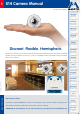
EN S14 Camera Manual The HiRes Video Company HiRes 6 Megapixel 4096 x 1536 Software zoom EN Skyline Format free Each image format freely definable 30 Frames/s VGA (640 x 480) 30 F/s Mega Virtual PTZ Digital pan, tilt, zoom Backlight Safe using CMOS without mechanical iris Discreet. Flexible. Hemispheric. With the S14D FlexMount, two sensor modules featuring microphones are connected to a concealed camera housing via cables up to 2 m/6.6 ft long.
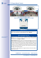
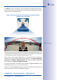
/148 S14 Camera Manual: Contents 180° panorama 180° panorama One camera, two surveillance areas: Indoor entrance area (left) and outdoor entrance area (right) MOBOTIX Seminars MOBOTIX offers inexpensive seminars that include workshops and practical exercises. For more information, visit www.mobotix.com > Seminars. Notes And Copyright Information Additional information: www.mobotix.
/148 Contents Contents Foreword 8 The MOBOTIX Concept 10 Innovative Hemispheric Technology 12 Superior Storage Solution 16 Added Security Value 18 Cost Benefits And Technical Advantages 20 1 An Overview Of The S14 FlexMount 22 1.1 Versions and Product Characteristics: 22 1.2 Hemispheric Image Views 26 1.2.1 1.2.2 Overview Details (Sample Views For One Sensor) 26 28 1.3 Main Advantages Of The S14 FlexMount 32 1.3.1 New Features Compared To M12-DevKit 33 1.
/148 S14 Camera Manual: Contents 1.10.8 1.10.9 1.10.10 1.10.11 1.10.12 1.10.13 1.10.14 MX-Patch-Box MX-NPA-Box MX-GPS-Box MX-232-IO-Box ExtIO Function Expansion Mx2wire+ Media Converter Product Preview 61 62 62 62 63 63 63 2 Installation 64 2.1 Determining The Installation Position 64 2.1.1 2.1.2 2.1.3 Positioning A Hemispheric Camera S14D FlexMount Installation Options S14M FlexMount Installation Options 65 70 75 2.2 Before Mounting 76 2.2.1 2.2.2 2.2.3 2.2.4 2.2.5 2.2.6 2.2.7 2.2.8 2.2.
/148 Contents 3 Operating The Camera 98 3.1 Manual and Automatic Operation – Overview 98 3.1.1 3.1.2 3.1.3 Manually Using A Computer In The 10.x.x.x IP Address Range Automatically Using MxControlCenter Or MxEasy Automatically Using DHCP 99 100 101 3.2 First Images And The Most Important Settings 102 3.2.1 3.2.2 3.2.3 3.2.4 3.2.5 3.2.6 3.2.
/148 S14 Camera Manual: Contents 3.6.13 RoHS Declaration 3.6.14 Disposal 3.6.15 Disclaimer 143 143 144 Important Notes Electrical Installation Electrical systems and equipment may only be set up, changed and maintained by a qualified electrician or under the direction and supervision of a qualified electrician in accordance with the appropriate electrical guidelines.
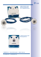
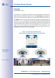
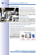
/148 S14D: Dual Camera System With Dual Imaging, Giving Up To 6 Megapixel Resolution S14M: Mono Camera System With Integrated Lens © MOBOTIX AG • Security Vision Systems • Made in Germany www.mobotix.com • sales@mobotix.
/148 S14 Camera Manual: Foreword Foreword Dear MOBOTIX customer, Congratulations on purchasing a highly efficient and discreet premium network camera ”Made in Germany.” MOBOTIX is proud to present the S14 FlexMount, a weatherproof system (IP65), characterized primarily by sensor modules that can be flexibly mounted. In the S14D, two lenses with a sensor board and a microphone are connected to the base module via a 2 m/6.6 ft long cable.
/148 The S14M version has a hemispheric sensor module (day or night) integrated into the camera housing. The housing can be placed discreetly behind a wall/ceiling or stainless steel panel up to 6.4 mm/0.25 in thick. S14M – Camera with hemispheric sensor module for concealed installation behind a wall or ceiling panel HiRes 180° panorama 180° panorama This manual starts with an overview of the innovative, decentralized MOBOTIX concept.
/148 S14 Camera Manual: The MOBOTIX Concept The MOBOTIX Concept HiRes Video Innovations and Technology Leader 3 Mega Since it was founded in 1999, the listed German company MOBOTIX AG has been regarded as the leading pioneer in network camera technology and its decentralized concept has made high-resolution video systems cost-efficient. 1,536 lines Mega MOBOTIX has been an exclusive producer of megapixel cameras for years and is the global leader in highresolution video systems.
/148 The Decentralized MOBOTIX Concept Unlike other systems, with the decentralized MOBOTIX concept, every camera features a high-speed computer, and, if necessary, a digital long-term memory (MicroSD Card) can be integrated to provide days of recording time. The PC or the video control center is required only to view and control the cameras (PTZ), not to evaluate and record video.
/148 S14 Camera Manual: Innovative Hemispheric Technology Innovative Hemispheric Technology The Hemispheric Camera The primary components of a hemispheric camera include a fisheye lens, a high-resolution image sensor, and image correction software that is integrated into the camera. Using an ultra-wide angle fisheye lens, the hemispheric camera captures a 180°-hemispheric image of the room and projects it onto a high-resolution image sensor.
/148 Less Cameras Thanks To Panoramic Views The perspective of the hemispheric image can also be transformed into an ultra-wide angle panoramic view spanning 180° if the camera is mounted on a wall, providing a wall-to-wall view of the room without any blind spots. It offers a substantially better view of the scene, compared to other cameras, and it also results in the need for fewer cameras overall. When ceiling mounted, one camera can also capture an entire room by two opposite panoramic views.
/148 S14 Camera Manual: Innovative Hemispheric Technology High-Resolution 180° Panorama The perspective of the hemispheric image can also be transformed into an ultra-wide angle panoramic view spanning 180° if the camera is mounted on a wall, providing a wall-to-wall view of the room without any blind spots. It offers a substantially better view of the scene, compared to other cameras, and it also results in the need for fewer cameras overall.
/148 Select From Several Image Views The surround function of a single S14 sensor module (ceiling-mounted) replaces four conventional cameras and shows four different directions simultaneously in quad view on a monitor. Virtual PTZ is available for each of the four views. Together with the 180° panorama, the S14 can deliver two more views simultaneously, making it possible to see the overview and to focus on two scenes at the same time (”Panorama Focus” display mode).
/148 S14 Camera Manual: Superior Storage Solution Superior Storage Solution MOBOTIX Storage Concept Without Bottlenecks These days, video data is normally pre-processed and stored centrally on a PC or DVR using video management software. Video and audio streams from all installed cameras are directed to this central device. This can quickly cause data bottlenecks for high-resolution cameras, in particular.
/148 SD Card Memory Reduces Recording Costs MOBOTIX cameras are also able to record up to 64 GB of video in their integrated memory. Thanks to this high storage capacity and the option of recording only the sequences in which an event occurs, external storage devices such as hard drives are rarely required. This saves on recording devices and network infrastructure and reduces the maintenance cost of mechanical components such as hard drives or fans.
/148 S14 Camera Manual: Added Security Value Added Security Value Robust, Low-Maintenance Technology The real added value of MOBOTIX products is reflected in characteristics such as enhanced functionality, long life and robustness. In general, MOBOTIX cameras have no moving parts. This makes the cameras very resistant to wear and tear, and reduces both maintenance costs and power consumption.
/148 Sound Increases The Chance Of Detection In the event of an alarm, MOBOTIX cameras can turn on their built-in microphones and record lip-synchronous audio. They are therefore an even greater help in analyzing a situation and easing clarification. In addition, the video system can be used for bidirectional communication via a loudspeaker/microphone. No Problems With Backlight MOBOTIX cameras are not adversely affected by the glare from direct sunlight.
/148 S14 Camera Manual: Cost Benefits And Technical Advantages The Most Important MOBOTIX Cost Benefits 1 2 3 4 5 6 7 8 9 10 Increased Resolution Reduces Amount Of Cameras Needed 1536 lines, high-resolution sensors give a better overview and allow monitoring an entire room with just one camera. Reduced Installation Costs At Any Distance Standard Ethernet connection enables the use of common network components such as fiber, copper and wireless (WLAN).
/148 The Most Important MOBOTIX Technical Advantages High-Resolution Digital Image Instead Of TV Quality Megapixel sensor and image processing inside the camera generate sharp images with a higher resolution than HDTV, allowing them to be recognized as evidence in a court of law. Hemispheric Technology For An Overview With No Blind Spots 360° allround view or 180° widescreen image, corrected for perspective; only one camera is needed to view the entire room or train platform without any blind spots.
S14 Camera Manual: An Overview Of The S14 FlexMount 1 An Overview Of The S14 FlexMount 1.1 Versions and Product Characteristics: am ete r: 5 2 in 0 mm/ Di 22/148 S14 FlexMount: Perfect For When Discretion Is Needed Some application scenarios benefit from a surveillance camera that is present, but does not attract attention. With the S14 FlexMount, MOBOTIX is presenting an IP video system with an especially discreet appearance, enabling a flexible range of applications.
/148 Versions and Product Characteristics: S14D: Dual Camera System With Double Images Up To 6 Megapixels The S14D (D = Dual), the second version, features one or two hemispheric sensor modules, each with an integrated microphone and two status LEDs, which can be connected to the base module via cables up to 2 m/6.6 ft long. www.mobotix.com, go to Products > S14 FlexMount and open the basket, which contains the Product Configurator.
/148 S14 Camera Manual: An Overview Of The S14 FlexMount Separate Housing And Lens Installation – Weatherproof According To IP65 The S14 FlexMount’s flat housing, including long-term flash memory (MicroSD card up to 64 GB) and all internal and external connectors (Ethernet, MiniUSB, MxBus, microphone, speaker), can be installed discreetly and with optimal protection behind a wall or ceiling panel so that only the lens units in their protective housings are visible in the room.
/148 Versions and Product Characteristics: Fast, Simple Cabling The MOBOTIX S14 FlexMount (S14D and S14M) requires just one cable for data and power to be connected to a PoE switch and thereby to any expandable Ethernet network. There are two options for a weatherproof connection of the network cable to the S14 housing.
/148 S14 Camera Manual: An Overview Of The S14 FlexMount 1.2 Hemispheric Image Views 1.2.1 Overview Featuring hemispheric L11 lenses, the S14 FlexMount offers all the image views known from MOBOTIX’s other hemispheric cameras, including Panorama, Panorama Focus, Double Panorama, Full Image, Normal and Surround. What’s new on the S14D is that the selected view can be displayed as a dual image that combines both sensor modules.
Hemispheric Image Views 27/148 180° Panorama – Full Image (Wall-Mounted) S14D: Different image views can be selected (figures show examples only) for two sensor modules 180° Panorama – Panorama Focus (Wall-Mounted) Panorama Focus – Normal View ”Zoom” (Wall-Mounted) Double Panorama (Ceiling-Mounted) – Panorama Focus (Wall-Mounted) © MOBOTIX AG • Security Vision Systems • Made in Germany www.mobotix.com • sales@mobotix.
/148 S14 Camera Manual: An Overview Of The S14 FlexMount 1.2.2 Details (Sample Views For One Sensor) High-Resolution 180° Panorama (Wall-Mounted) The hemispheric image (original full image) can also be transformed into an ultra-wide angle panoramic view spanning 180° if the camera is mounted on a wall, providing a wall-to-wall view of the room with no blind spots. It offers a substantially better view of the scene, compared to other cameras, and it also results in the need for fewer cameras overall.
Hemispheric Image Views 29/148 Double Panorama For A Simultaneous View In Two Directions (Ceiling-Mounted) When the camera is mounted in the center of the ceiling in a room, the ”Double Panorama” display mode provides a corrected panorama image of both halves of the room. It corresponds roughly to the situation of personally standing in the middle of the room and being able to look both forwards and backwards at the same time. This is a superb overview for the user – provided by a single sensor module.
/148 S14 Camera Manual: An Overview Of The S14 FlexMount Full Image And Normal View The full image view displays the circular, non-software-corrected original fisheye view of the entire image sensor, just as it is stored in full image recording. The ”Normal” view displays a corrected image section that is easier to pan, tilt or zoom. Original fisheye image: full image Corrected image section: Normal © MOBOTIX AG • Security Vision Systems • Made in Germany www.mobotix.com • sales@mobotix.
/148 Hemispheric Image Views Surround View (Quad View), Based On The Corrected Full Image The ”Surround” display mode (ceiling-mounted) replaces four conventional cameras for each sensor module and shows four different directions simultaneously in quad view on the monitor. The preset North position can be moved to any direction in the image. The camera generates the other three directions (East, South, West) automatically and stores them as separate views.
/148 S14 Camera Manual: An Overview Of The S14 FlexMount 1.3 Main Advantages Of The S14 FlexMount The high-resolution S14 FlexMount is not just a universally deployable, highly innovative and easily concealable camera system. Featuring a faster microprocessor and updated system platform, it also replaces the existing M12 DevKit including MxLink.
Main Advantages Of The S14 FlexMount Flexible And Futureproof The system can easily be matched to suit the location’s requirements, thanks to a range of available sensor modules (S14D only). Replacing the sensor modules at a later stage to change the focal lengths (coming soon), or upgrading from one to two sensor modules, is quick and easy. 1.3.
/148 S14 Camera Manual: An Overview Of The S14 FlexMount 1.4 General MOBOTIX Camera Functions Like all MOBOTIX cameras, the S14 line has a variety of software functions: from motion detection and long-term storage right through to alarm notification via video IP telephony. Unlike camera systems from other manufacturers, buying and installing additional software on the computer is thus unnecessary. It is possible to use a web browser.
/148 General MOBOTIX Camera Functions Voice Over IP Moreover, MxPEG provides for lip-synchronous audio and two-way communication between the camera and a computer. Room surveillance is possible using a browser (Internet Explorer), MxControlCenter or MxEasy. Customized alarm notification on your mobile phone or via Internet telephony is just as easy as event-controlled voice messages directly from the camera.
/148 S14 Camera Manual: An Overview Of The S14 FlexMount Event And Time Controlled Recording Just like triggering event-controlled recording upon detecting movements in the image, the camera can also record when the volume detected by the microphone exceeds a certain trigger value. Using scheduled daily recording, time tasks can start or stop video recording, upload images to a website, or send e-mails with video/audio clips. Vacation times and holidays can be programmed.
General MOBOTIX Camera Functions 37/148 MxControlCenter – Professional Video Management, Free Of Charge Instead of using a web browser, you can download and install the free-of-charge MxControlCenter from the MOBOTIX website. This program allows live images from highresolution MOBOTIX cameras to be displayed on one monitor with sound. In addition, MxControlCenter can activate alarms with lip-synchronous audio and also enables convenient event search.
/148 S14 Camera Manual: An Overview Of The S14 FlexMount All settings selected in MxEasy (for example, virtual camera position, zoom, brightness, volume, microphone sensitivity, image storage, signal outputs) are usable immediately and are stored instantly in the configuration of the corresponding camera. The calendar function integrated in the Alarm Planner provides access to innovative features for scheduled settings of one or more cameras.
General MOBOTIX Camera Functions 39/148 • Time Tables that handle customized holidays and vacations are used to control the camera’s arming, image recording, actions, messaging, logos, the obscure image function as well as other features • Remote signaling for master/slave cameras, where the master camera controls the arming status of the slave cameras allows all slave cameras to be armed using a key switch connected to the master camera, for example.
/148 S14 Camera Manual: An Overview Of The S14 FlexMount 1.5 Lens Options MOBOTIX S14 models ship with standard L11 fisheye lens units with a 180° horizontal image angle. The integrated virtual PTZ features of the camera software or MxControlCenter/ MxEasy properly correct the lens distortion that is specific to each of the lenses. These lenses deliver good image quality even when using maximum digital zoom.
/148 Lens Options Lenses L11 L22* L32* L43* L65* L135* *L22 Lenses... L135 available for S14D soon 11 mm 22 mm 32 mm 43 mm 65 mm 135 mm S14M only available with L11 lens Original image 35 mm equivalent Nominal focal length 1.8 mm 4 mm 6 mm 8 mm 12 mm 25 mm Aperture 2.0 2.0 2.0 2.0 2.0 2.5 Horizontal image angle 180° 90° 60° 45° 31° 15° Vertical image angle 160° 67° 45° 34° 23° 11° Dist. 1 m m m m m m m Image width infinite 2.0 1.1 0.8 0.5 0.
/148 S14 Camera Manual: An Overview Of The S14 FlexMount MX-S14M-SEC-NIGHT-N11 MX-S14D-SEC S14 FlexMount Hardware Features MX-S14M-SEC-D11 1.6 IP65 IP65 IP65 Ethernet/MiniUSB/MxBus/MicroSD X X X MicroSD slot (internal DVR, max.
/148 Software Features For All Camera Modules Software Features For All Camera Modules D24M Q24M Secure Model D14 IT Model S14M M24M Web Model M12 Basic Model 1.
/148 S14 Camera Manual: An Overview Of The S14 FlexMount 1.8 Technical Data Technical Data S14 FlexMount Model versions MX-S14M-SEC (day), MX-S14M-SEC-NIGHT (night), MX-S14D-SEC (all combinations of day/night sensor modules) Lens options 11 mm (on 35 mm equiv.), horizontal image angle: 180° Sensitivity Color sensor: 1 lux (t = 1/60 s), 0.05 lux (t = 1/1 s) Black-and-white sensor: 0.1 lux (t = 1/60 s), 0.
/148 Technical Data Technical Data S14 FlexMount Certification EMV (EN 55022, CISPR 22, EN 55024, EN 61000-6-1+2, FCC Part 15B, AS/NZS3548), EN 50121-4, EN 50155 Power supply Year-round Power-over-Ethernet (IEEE 802.3af/t); PoE class variable (class 2 set by default), approx. 4.5 W Operating conditions IP65, –30°C to +60°C (–22°F to 140°F) Dimensions/weight S14M W x H x D: 115 x 130 x 39.4 mm (installation dimensions); weight: approx.
/148 www.mobotix.com, go to Products > S14 FlexMount and open the basket, that contains the Product Configurator. Use this to order the required parts in any of the available colors S14 Camera Manual: An Overview Of The S14 FlexMount 1.9 S14 FlexMount – Scope Of Delivery 1.9.1 S14D FlexMount – Scope Of Delivery 1.1 M.9 M.8 1.2 M.7 1.4 1.3 M.6 1.5 M.5 M.4 1.6 1.7 M.3 1.8 M.2 M.1 1.9 1.11 1.10 © MOBOTIX AG • Security Vision Systems • Made in Germany www.mobotix.com • sales@mobotix.
S14 FlexMount – Scope Of Delivery Item Number 1.1 1 Part Name Base module (camera housing with base plate) 1.2 1 Housing cover for S14D (installed) 1.3 1 Stainless steel flat-head Allen screw M4x8 (installed) 1.4 1 Washer 1.5 3 Sealing plug, blue, small (sensor modules, USB, inserted) 1.6 1 Sealing plug, blue, large (Ethernet patch cable, installed) 1.7 1 1.
/148 S14 Camera Manual: An Overview Of The S14 FlexMount Base Module S14D The MOBOTIX S14D consists of a housing, a housing cover and a base plate for attaching the camera. LED defaults: 1 Power (on), Error (flashes) 2 Recording (flashes) 1 MicroSD card 2 LEDs Base plate L R 130 mm/5.12 in Keys S14D housing cover Pressure compensation element Bayonet catch Triple cable retainer 115 mm/4.
/148 S14 FlexMount – Scope Of Delivery Internally-Accessible Connections On The S14D The MOBOTIX S14D provides the following internal connections that can be accessed once the cover plugs and housing cover are removed: LSA+ terminal Ethernet installation cable Screw terminals MxBus, microphone, speaker MOBOTIX-RJ45 or MxBus, microphone, speaker Ethernet installation cable or MxBus, microphone, speaker Before laying the Ethernet installation cable, remove the bayonet catch and replace the Ethernet pat
S14 Camera Manual: An Overview Of The S14 FlexMount 1.9.2 S14D FlexMount – Dimensions 115 mm/4.53 in 130 mm/5.12 in M6 47.5 mm/1.87 in 100 mm/3.94 in 110 mm/4.33 in 100 mm/3.94 in 8.5 mm/0.33 in 50/148 Diam. 5.5 mm/ 0.22 in 13.5 mm/0.53 in Attaching The Base Module Slots M6 tap holes © MOBOTIX AG • Security Vision Systems • Made in Germany www.mobotix.com • sales@mobotix.
S14 FlexMount – Scope Of Delivery 33.5 mm/1.32 in 5 mm/ 0.2 in © MOBOTIX AG • Security Vision Systems • Made in Germany www.mobotix.com • sales@mobotix.
/148 S14 Camera Manual: An Overview Of The S14 FlexMount 1.9.3 L11 Sensor Module – Scope Of Delivery 3.1 3.2 3.6 Sensor module including status LEDs and microphone 3.3 3.5 3.4 Item Number 3.1 1 Part Name Sensor module with glued-on sealing 3.2 1 L11 lens (installed) 3.3 1 Dome (installed) 3.4 1 Cable retainer with bayonet catch 3.5 1 Sealing plug, blue, small (sensor modules, USB, inserted) 3.
/148 S14 FlexMount – Scope Of Delivery Front View Of Sensor Module LED defaults: 2 1 Power (on), Error (flashes) 2 Recording (flashes) Diam. 50 mm/2 in 1 LEDs L11 sensor module housing Microphone Diam. 50 mm/2 in Rear View Of Sensor Module Diam. 43 mm/1.7 in Markers for top Sensor cable connection L11 sensor module housing Pressure compensation element top = top border of image (North) Diam. 43 mm/1.7 in 1.9.4 L11 Sensor Module – Dimensions 58 mm/2.28 in 15.3 mm/0.6 in Diam. 43 mm/1.7 in 30.
/148 www.mobotix.com, go to Products > S14 FlexMount and open the basket that contains the Product Configurator. Use this to order the required parts in any of the available colors S14 Camera Manual: An Overview Of The S14 FlexMount 1.9.5 S14M FlexMount – Scope Of Delivery 2.1 M.9 2.2 M.8 2.3 M.7 M.6 2.4 M.5 M.4 2.6 M.3 2.5 2.7 M.2 2.8 M.1 2.9 2.10 2.13 2.11 2.12 © MOBOTIX AG • Security Vision Systems • Made in Germany www.mobotix.com • sales@mobotix.
S14 FlexMount – Scope Of Delivery Item Number 2.1 1 Part Name Camera housing (with base plate) 2.2 1 Lens (installed) 2.3 1 Dome (installed) 2.4 1 Housing cover for S14M (installed) 2.5 3 Stainless steel flat-head Allen screw M4x8 (installed) 2.6 1 Washer 2.7 1 Sealing plug, blue, small (sensor modules, USB, inserted) 2.8 1 Sealing plug, blue, large (Ethernet patch cable, installed) 2.9 1 2.
/148 S14 Camera Manual: An Overview Of The S14 FlexMount Camera Housing S14M The MOBOTIX S14M consists of a base plate for attaching the camera, a housing with built-in lens, and a housing cover. LED defaults: 1 MicroSD card 2 LEDs Base plate R L Keys 130 mm/5.12 in 1 Power (on), Error (flashes) 2 Recording (flashes) Lens with dome S14M housing cover Pressure compensation element Bayonet catch Triple cable retainer 115 mm/4.
/148 S14 FlexMount – Scope Of Delivery Internally-Accessible Connections On The S14M The MOBOTIX S14M provides the following internal connections that can be accessed once the cover plugs and housing cover are removed: LSA+ terminals Ethernet installation cable Screw terminals MxBus, microphone, speaker MOBOTIX-RJ45 or MxBus, microphone, speaker Ethernet installation cable or MxBus, microphone, speaker Before laying the Ethernet installation cable, remove the bayonet catch and replace the Ethernet pa
/148 The drilling templates can be found at the end of the manual S14 Camera Manual: An Overview Of The S14 FlexMount 1.9.6 S14M FlexMount – Dimensions Always print or copy drilling templates in their original size 115 mm/4.53 in 130 mm/5.12 in M6 47.5 mm/1.87 in 100 mm/3.94 in 8.5 mm/0.33 in 110 mm/4.33 in 100 mm/3.94 in Diam. 5.5 mm/ 0.22 in 13.5 mm/0.53 in Attaching The Camera Housing Slots M6 tapped slots © MOBOTIX AG • Security Vision Systems • Made in Germany www.mobotix.
/148 S14 FlexMount – Scope Of Delivery 48 mm/1.89 in 39.5 mm/1.56 in 33.5 mm/1.32 in 5 mm/ 0.2 in © MOBOTIX AG • Security Vision Systems • Made in Germany www.mobotix.com • sales@mobotix.
/148 S14 Camera Manual: An Overview Of The S14 FlexMount 1.10 Available Accessories 1.10.1 Extension For Sensor Module Order no.: MX-S14-OPT-MK-EX Each of these extensions increases the installation depth by 40 mm/1.6 in. They can be mounted directly onto the sensor modules themselves or onto existing extensions. 1.10.2 Ceiling/Wall Installation Set Order no.
Available Accessories 61/148 1.10.5 MiniUSB Cable to USB A Socket Order no.: MX-CBL-MU-STR-AB-05/2/5 (straight) USB-based storage media (for example, USB hard drives) can be connected directly to the S14 with this cable, which is up to five meters long. 1.10.6 Ethernet Patch Cable For Bayonet Catch Order no.: MX-OPT-CBL-LAN-1/2/5/10 (length: 1 m/2 m/5 m/10 m) The MOBOTIX-developed special cable can be installed in a waterproof manner and has an integrated sealing gasket. Every S14 ships with a 0.
/148 S14 Camera Manual: An Overview Of The S14 FlexMount 1.10.9 MX-NPA-Box Order no.: MX-OPT-NPA1-EXT The MX-NPA-Box is a weatherproof PoE injector conforming to the IEEE 802.3af standard and is designed to connect to a MOBOTIX camera external voltage sources (12 to 57 V DC). The MX-NPA-Box is equipped with the PatchBox’s weatherproof and extremely compact exterior housing (protection class IP65, –30°C to +60°C/–22°F to +140°F), which means it can also be installed in the space of the Outdoor Wall Mount.
/148 Available Accessories 1.10.12 ExtIO Function Expansion Order no.: MX-ExtIO The device, which is suitable both for on-wall and in-wall installations, contains a powerful speaker, microphone, infrared motion sensor, ambient temperature sensor, two input and two output contacts and two illuminated buttons. It is ideal for door communication, elevators, access control, etc. The ExtIO is suitable for use as direct connection to the S14 via a MiniUSB cable (max.
/148 S14 Camera Manual: Installation 2 Installation The S14 FlexMount is designed for concealed installation in ceilings, walls, behind panels or in existing or specially manufactured housings. The independent sensor models, each with a max. 2 m/6.6 ft long cable, mean the S14D can offer a number of options when selecting the installation location. The installation position of the sensor modules is crucial here.
/148 Determining The Installation Position 2.1.1 Positioning A Hemispheric Camera A hemispheric camera is primarily suited to providing an excellent overview, and less suitable for more exact details. Due to its inherent physical and optical properties, the precision of the lens decreases as the distance from the lens grows. This means that the maximum usable image area greatly varies with the purpose of the camera. People, for example, may be identified very well at distances of up to 1.
/148 S14 Camera Manual: Installation Rectangular Rooms When viewing a 360° panaroma image in the browser, you will notice that the top and bottom of the image are not fully visible, i.e., some image information has been clipped. This is not the fault of the camera, but intended behavior that aims at achieving the best possible utilization of the image sensor by the camera software.
/148 Determining The Installation Position Wall-Mounting To make optimal use of the high-resolution 180° panorama functionality of a hemispheric camera, the lens or sensor module must be mounted on an inside or outside wall. The entire hemisphere of the room directly in front of the camera is then effectively monitored, from the wall on the left of the camera to the wall on the right.
/148 S14 Camera Manual: Installation Selecting An Appropriate Camera Position During installation, ensure that the camera is focused on the most important areas of the room as directly as possible in order to provide the desired level of detail recognition (camera focus). The S14 should be installed on a wall such that the two arrows on the back of the sensor module housing (S14D) or the rounded side of the camera housing (S14M) are pointing towards the ceiling. 2.50 to 3.50 m/8.2 to 11.
/148 Determining The Installation Position Greater wall thicknesses can also be bridged by attaching several extensions. The sensor module is secured from behind by a nut and a locknut. 40 mm/ 1.6 in 40 mm/ 1.6 in 40 mm/ 1.6 in 40 mm/ 1.6 in Multiple extensions can be added (EN 50155 vibration resistance was tested with one extension added) Wall Installation With 15° Wedge For Image Optimization 2.50 to 3.50 m/8.2 to 11.
/148 S14 Camera Manual: Installation 2.1.2 S14D FlexMount Installation Options Using One Or Two Sensor Modules You can decide for yourself with the S14D whether you want to use the camera with one or two sensor modules. You can upgrade or downgrade the system at any time. www.mobotix.com, go to Products > S14 FlexMount and open the basket that contains the Product Configurator.
/148 Determining The Installation Position Ceiling-Mounted Indoor installation is mostly on suspended ceilings and is extremely easy. A round hole with a diameter of 45 mm/1.77 in is all that is needed, through which a S14D sensor module with connection cable and attached ferrite is pushed down through the ceiling panel, fixed from behind using a nut and then connected to the concealed base module hidden behind a ceiling panel (connector and lock). Step 3: Secure sensor module with nut 3 Diam.
/148 S14 Camera Manual: Installation The S14D can, however, also be deployed at shorter distances between the two sensor modules with surprising results: • Two adjacent areas separated by a dividing wall, shelves, floor or other form of screen can be captured with no blind spots using a S14D. The S14D monitors two separate rooms • In L-shaped rooms, both sensor modules are simply positioned at right angles. A S14D therefore captures the entire room with no blind spots. Cable up to 2 m/6.
/148 Determining The Installation Position Product preview: SurroundMount module with 2 x L11 sensor modules SurroundMount S14D SurroundMount: 6 megapixel 360°camera Wall-Mounting Mounting with or without 15° wedge (accessories) Diam. 50 mm/2 in* Diam. 45 mm/1.77 in Mounting a S14D sensor module on a wall, for example, on basic partition walls or fake walls with cavities behind the wall covering, is just as easy as mounting on a ceiling. Drill a hole 45 mm/1.
/148 S14 Camera Manual: Installation Mixed Ceiling- And Wall-Mounting By mounting a sensor module on the ceiling of a room and at the same time attaching the second sensor module to an outside wall of this room, both the inside and the outdoor area can be captured with a single S14D at minimal installation cost. Example: Kiosk Simultaneous capture of the entire sales floor and the area outside the entrance with stand-up tables. Cable up to 2 m/6.6 ft in length Cable up to 2 m/6.
/148 Determining The Installation Position 2.1.3 S14M FlexMount Installation Options Unlike the S14D, the S14M has just one lens, which does not have a flexible sensor cable, but is directly connected to the camera housing. Contrary to conventional mono cameras, the S14M has come up with a very neat trick: The camera housing can be mounted concealed behind a wall up to 6.4 mm/0.25 in thick (wood paneling, stainless steel panel, etc.) with a round opening measuring 34 mm/1.34 in.
/148 S14 Camera Manual: Installation 2.2 Before Mounting This section of the manual provides an overview of the variety of S14 connection options, the preparatory steps and the tools required for mounting. 2.2.1 Overview Of Cable Connections The following cables can be used with the S14 (see also Section 1.
/148 Before Mounting Caution Only MOBOTIX cables may be used for the Ethernet and USB connection as well as to the sensor modules (S14D) to ensure the camera remains permanently watertight. Ethernet for LAN MiniUSB Sensor cable Unused connections must be secured using appropriate cable plugs and by closing the corresponding locks to protect the inside of the housing against water and dust.
/148 S14 Camera Manual: Installation Inserting And Locking MOBOTIX Cables And Plugs The corresponding lock must be applied or closed again after inserting one of the cables or plugs indicated above into the S14: Patch cable MiniUSB/sensor cable 1. Insert the cable/plug. 1. Insert the cable/plug. 2. Attach bayonet catch. 2. Push the triple retainer down (towards the base plate) until it clicks into place. 3. Turn the bayonet catch to the right. 2.2.
/148 Before Mounting 2.2.3 Network Connection With MOBOTIX Patch Cable The supplied MOBOTIX patch cable can be used to connect the camera to an MX-PatchBox, an MX-NPA-Box or to a standard network port. Connecting The Patch Cable To The Camera First remove the blue bayonet catch and the blue sealing plug in the left-hand connector on the S14. Then insert the MOBOTIX patch cable into the camera and secure the cable using the bayonet catch.
/148 S14 Camera Manual: Installation 2.2.4 Network Connection With Installation Cable As an alternative to connection to an MX-Patch-Box, MX-NPABox or standard network port, you can also connect the S14 directly to an installation cable. Since the housing cover of the camera must be opened for this purpose, this working Installation cable step in a S14M must be carried out before mounting the camera as the housing cover is no longer accessible once it has been mounted.
/148 Before Mounting 2.2.7 Using MxBus Modules The MxBus camera connector is located under the housing cover (clamps 5 and 6 of the screw clamps) and allows the operation of additional modules for expanding functionality (e.g. connection of an MX-GPS-Box for determining time and position). MxBus was optimized specifically for the use of existing two-wire cables. The terminal connector has two connectors to connect an MxBus module (other MxBus modules can then be connected from there).
/148 S14 Camera Manual: Installation 2.2.9 Replacing The MicroSD Card Replace the MicroSD card only if the camera is disconnected from the power supply! If the 4 GB MicroSD card supplied needs to be replaced (for example, with a 64 GB MicroSD card), it is best to do so before the camera is installed. MicroSD cards should only be replaced when the camera is disconnected from the power supply. 1.
/148 Before Mounting • Pencil to mark the drill holes • Potentially LSA+ tool for fitting an installation cable onto the LSA terminals of the camera • Hole saw or Forstner drill with 44 to 45 mm/1.77 in diameter for the S14D sensor modules or with 35 mm/1.38 in diameter for the S14M lens • Soft cotton cloth to clean the front of the lens after installation 2.2.
/148 S14 Camera Manual: Installation 2.3 LED defaults: 1 Power (on), Error (flashes) 2 Recording (flashes) Installing The S14D FlexMount 1 MicroSD card 2 LEDs Base plate R L 130 mm/5.12 in Keys S14D housing cover Pressure compensation Bayonet catch element Triple cable retainer Slits for cable ties The drilling templates can be found at the end of the manual Always print or copy drilling templates in their original size 115 mm/4.
/148 Installing The S14D FlexMount 2.3.2 Attaching And Connecting The S14D Sensor Modules Before installing the sensor modules, make sure that the sensor cables will reach the intended mounting position without placing a strain on the cables. Further information on the individual camera connectors can be found in Section 2.2.1, «Overview Of Cable Connections». 1. Drill the hole for the sensor module at the intended mounting position (arrow on the back of the sensor module pointing ”Up”). 2.
/148 S14 Camera Manual: Installation 7. If a 15° wedge has been fitted, the second wedge sealing and the second wedge must now be pushed over the sensor cable, any installed extensions and the sensor module (the thicker side of the wedge is at the bottom) may need to be shifted to ensure that the nut is properly positioned on the back. 8. Feed the sensor cable through the nut and secure the sensor module and mounted extensions using that nut.
/148 Installing The S14D FlexMount 3. Turn the extension in a clockwise direction until it clicks into place (viewed from the right). The extension will lock automatically and will not turn, even if the nuts are loosened. Note Make sure that the extensions are always connected as described in Step 2. Attaching the extensions incorrectly will damage the bayonet catch and may result in the nuts not being properly attached. Removing Extensions Proceed as follows to loosen and undo an extension lock: 1.
/148 S14 Camera Manual: Installation 2.4 LED defaults: 1 Power (on), Error (flashes) 2 Recording (flashes) Installing The S14M FlexMount 1 MicroSD card 2 LEDs Base plate R L 130 mm/5.12 in Keys Lens with dome S14M housing cover Pressure compensation element Bayonet catch Triple cable retainer Slits for cable ties 115 mm/4.53 in 2.4.
Installing The S14M FlexMount 89/148 Attachment To A Rear Wall If the S14M is attached with the base plate on a rear wall (and then, for example, to a separate stainless steel cover), the camera can be mounted in just a few steps: 1. If necessary, mark the drill holes at the intended mounting position, drill the holes for the base plate and hammer in the 6 mm dowels supplied. 2.
/148 S14 Camera Manual: Installation 2.5 Network And Power Connection, Additional Cables 2.5.
/148 Network And Power Connection, Additional Cables 2.5.2 Network Cabling For S14 With Patch Cables 1. Remove housing cover and cable plugs: Loosen the Allen screw on the housing cover of the S14 and remove it. Push the cable plug in the camera out of the housing from the inside to the outside (red arrow). 2. Attach the cable ties: Feed one of the cable ties supplied through both slots in the circuit board underneath the LSA cutting clamp. 3.
/148 S14 Camera Manual: Installation 5. Connecting the cable wires: The individual wires of the installation cable can be connected to the LSA cutting clamp using an appropriate tool and in accordance with the EIA/TIA-568A or B standard used (see printed color coding above the clamp; see red arrow in the illustration below). Caution Make sure that all cable end offcuts are removed from inside the camera.
/148 Network And Power Connection, Additional Cables 2.5.3 Connecting Additional Cables Additional cables can be fed through the free opening in the housing, depending on the Ethernet connector used (patch cable or installation cable). If an installation cable is used, additional cables should be installed after the installation cable has been fitted. Ethernet via patch cable Additional cables (MxBus, microphone, speaker) 1. Replace any single wire plugs with appropriate cable plugs (M.
/148 S14 Camera Manual: Installation 2.5.4 PoE Variables The power consumption of the camera depends on the functions in use as well as any peripheral devices connected (see table). PoE classes 1, 2 or 3 may be selected in the browser-based user interface in order to optimally adjust the camera to your system design (PoE switch in use, emergency power concept, etc.). PoE Power Level Classes (IEEE 802.
/148 Network And Power Connection, Additional Cables 2.5.5 Power Supply Using A Switch 1. Connect the factory pre-installed cable of the camera to the Camera connector of the PoE adapter. 2. Connect the LAN/Power connector of the PoE adapter to the Ethernet connector of the switch/router or the Ethernet port. The IP addresses in the diagram are shown only as an example 3. Plug the RJ45 connector of the power supply unit into the PC/Power connector of the PoE adapter.
/148 S14 Camera Manual: Installation 2.5.6 Power Supply When Connected Directly To A Computer 1. Connect the factory pre-installed cable of the camera to the Camera connector of the PoE adapter. The IP addresses in the diagram are shown only as an example 2. Connect the PC/Power connector of the PoE adapter to the Ethernet port of the computer. 3. Plug the RJ45 connector of the power supply unit into the LAN/Power connector of the PoE adapter.
Network And Power Connection, Additional Cables 97/148 2.5.8 Camera Startup Sequence As soon as the power supply has been established, LEDs 1 and 2 will show the progress of the startup sequence. 1 2 LED defaults: 1 Power (on), Error (flashes) 2 Recording (flashes) R L • Booting: Immediately after connecting the power supply, the red LED lights up, blinks for two seconds, then stays on permanently red. A camera self-test is carried out at this point, and the entire system is started.
/148 Download the freeof-charge MxEasy and MxControlCenter software at www.mobotix.com S14 Camera Manual: Operating The Camera 3 Operating The Camera 3.1 Manual and Automatic Operation – Overview MOBOTIX cameras do not require any extra software. Thus, you can set up and operate the MOBOTIX camera using a JavaScript-enabled browser on all common operating systems (such as Windows, Linux, Macintosh, etc.). As an alternative, you can also use the MOBOTIX applications MxControlCenter and MxEasy.
Manual and Automatic Operation – Overview 3.1.1 99/148 Manually Using A Computer In The 10.x.x.x IP Address Range You can set up the camera’s network parameters using a browser and the embedded camera software. To do this, connect the camera to a computer or a network that is using a 10.x.x.x IP address range (see Section 3.2.1, «Manually Setting Up The Network Parameters In A Browser»).
/148 S14 Camera Manual: Operating The Camera 3.1.2 Automatically Using MxControlCenter Or MxEasy You can set up the camera’s network parameters using the free-of-charge video management software MxControlCenter or MxEasy (see Section 3.2.3 and Section 3.2.4). You can also use one of these applications to automatically configure the network parameters of MOBOTIX cameras that are not operating on the same IP address range as the computer. MxControlCenter software (free download from www.mobotix.
Manual and Automatic Operation – Overview 3.1.3 Automatically Using DHCP The camera can automatically obtain its network parameters using DHCP (Dynamic Host Configuration Protocol). This requires the network to have a functioning DHCP server (for example, a DSL router with activated DHCP server) and the camera must be booted using DHCP (see Section 3.2.7, «Starting The Camera With An Automatic IP Address (DHCP)»).
/148 S14 Camera Manual: Operating The Camera 3.2 First Images And The Most Important Settings Once the MOBOTIX camera has been connected to the network, you need to set up the camera’s network interface accordingly. This step involves setting up and checking the network parameters of the camera. If your network is already using an IP address in the 10.x.x.x range with a 255.0.0.0 network mask, you do not need to change the camera’s network parameters. You can access the camera directly (see Section 3.
First Images And The Most Important Settings 103/148 Linux/Unix: 1. Open a terminal as root user. 2. Enter the following command: ifconfig eth0:1 10.8.0.11 3. The computer is now also using the IP address 10.8.0.11 Mac OS X: 1. Open System Properties > Network. 2. Select Ethernet. In the Configuration field, select Manual and enter a 10.x.x.x IP address (for example, 10.8.0.11). 3. Click on Apply on the bottom right-hand side of the dialog box to assign the computer the IP address 10.8.0.11. 2.
/148 S14 Camera Manual: Operating The Camera 3.2.2 First Images And The Most Important Settings In The Browser Once the MOBOTIX camera has been connected to the power supply and to the network, you can access the user interface with the live camera image in the web browser. Internet Explorer, Firefox, Safari or any other graphical browser with activated JavaScript is suitable. It does not matter which operating system is used.
First Images And The Most Important Settings 105/148 Camera Views: Live, Player, MultiView The MOBOTIX camera automatically displays the live screen when it starts up (factory default setting). You can set a different start page in Admin Menu > Language and Start Page (for example, the Guest screen) to allow a restricted access to the live image.
/148 S14 Camera Manual: Operating The Camera 3.2.3 First Images And Network Parameter Configuration In MxControlCenter Download MxControlCenter for free from www.mobotix.com Installation Download the setup file from the MOBOTIX website to install the latest version. The latest versions are available at www.mobotix.com in the Support > Software Downloads > MxControlCenter section. To install MxControlCenter, simply double-click on the setup file and follow the instructions.
/148 First Images And The Most Important Settings MOBOTIX– Searching And Displaying MOBOTIX Cameras Launch MxControlCenter after successful installation by double-clicking on the shortcut that was created during installation or the executable file MxCC.exe in the installation directory on your computer. The Add Video Sources dialog box appears and the application automatically searches for MOBOTIX cameras in the local network when you launch the program for the first time.
/148 S14 Camera Manual: Operating The Camera Cameras Are Found But Are Located In A Different Subnet The symbols in the first column and the legend in the dialog box indicate whether you can access a particular camera directly from the MxControlCenter, which is the case for (OK) . Cameras designated with (different subnet) all cameras designated with are located in a different subnet. This usually applies to new cameras or cameras that have been reset to their factory settings.
First Images And The Most Important Settings Activate the Use this IP address/this range option if the IP address of a particular camera must be assigned manually (for networks with static IP addresses). Obtain the assigned IP address, subnet mask and standard gateway from your network administrator and enter the data. All you have to do is enter the range of IP addresses that includes the addresses of all of these cameras to reconfigure multiple cameras at the same time.
/148 S14 Camera Manual: Operating The Camera Editing The Video Source List Right-click on this list to open a shortcut menu from which you can select all video sources or cancel the selection. You can also use this method to remove from the list some or all of the video sources that you would not like to display or manage in MxControlCenter.
First Images And The Most Important Settings 111/148 3.2.4 First Images And Network Parameter Configuration In MxEasy Installing And Starting MxEasy Download the current version of MxEasy from the MOBOTIX website (www.mobotix.com > Support > Software Downloads in the MxEasy area). Double-click on the shortcut for the program or load the program file.
/148 S14 Camera Manual: Operating The Camera Reconfiguring Network Addresses Of Cameras *Bonjour: automatic recognition of network services in IP networks Using Bonjour*, MxEasy finds not only cameras on the same network as your computer, but also MOBOTIX cameras located in other subnets (the Invalid Network status).
First Images And The Most Important Settings 113/148 Here, you can jump directly to the main window of MxEasy with the current live camera image by activating the option Quick Start. However, some required detailed configurations may have to be made at a later time (for example, password protection, available bandwidth). For this reason, we recommend activating the option Complete integration and complete the remaining dialog boxes of the MxEasy Assistant until the main window appears.
/148 S14 Camera Manual: Operating The Camera 3.2.6 Starting The Camera With The Factory IP Address Passwords and camera settings will not be changed Under certain circumstances, you may have to reset the camera to its factory IP address. This could be the case, for example, if the IP address has been lost or the camera does not respond to the last known IP address. Proceed as follows to start up the camera with its factory IP address: 1.
First Images And The Most Important Settings 115/148 3.2.7 Starting The Camera With An Automatic IP Address (DHCP) If your network has a DHCP server, you can start the MOBOTIX camera with DHCP support. The camera automatically obtains an IP address from the DHCP server and announces the new network data. Please note that this announcement can only be heard if the camera is connected to an external speaker. 1.
/148 S14 Camera Manual: Operating The Camera 3.3 Virtual PTZ And Full Image Recording 3.3.1 Preparing The Virtual PTZ Function The virtual PTZ function allows you to use a mouse or joystick to continuously zoom in on images from the selected video source and ”virtually” move the enlarged image section within the entire image sensor area.
Virtual PTZ And Full Image Recording Operation Using USB Joystick A standard USB joystick can drastically improve vPTZ operation for the user – in the browser, in MxEasy, and in the MxControlCenter (however, MxCC is also equipped with a virtual joystick that can be operated using the mouse). Please first install the joystick on the PC according to the manufacturer’s instructions.
/148 S14 Camera Manual: Operating The Camera 3.3.2 Full Image Recording It is possible to record a full image, regardless of the live image stream that is being displayed. This ensures that the recording always contains the full image of the lens used, even though the operator may have used the vPTZ features to zoom into the image in order to examine a specific detail.
Virtual PTZ And Full Image Recording Activate/Deactivate Full Image Recording In The Browser To configure this feature, open the Setup Menu > Event Control > Recording dialog box and activate or deactivate the Full Image Recording option. © MOBOTIX AG • Security Vision Systems • Made in Germany www.mobotix.com • sales@mobotix.
/148 S14 Camera Manual: Operating The Camera 3.3.3 Special S14 Configuration In The Browser The MOBOTIX S14M and S14D with one or two D11/N11 sensor modules offer a range of special configuration options for the image settings due to their hemispheric lenses. Depending on where the camera is mounted (ceiling, wall or floor) and on the live image display preferred by the user, certain important basic settings and, if necessary, their adjustment must be configured when a S14 is first installed.
Virtual PTZ And Full Image Recording 121/148 Characteristics Of A S14M A S14M can only be fitted with an L11 lens due to design considerations. Because of this, a S14M acts the same as a Q24M Hemispheric. It allows the same types of installation (ceiling, wall, floor) and provides the same display modes. Configuration Of The S14 Basic Parameters Complete the steps described below in the browser window: 1. Log onto the camera and boot it as described in Section 3.2. 2.
/148 S14 Camera Manual: Operating The Camera Wall-Mounted: Setting And Correcting the Standard View ”Panorama” Camera live image with panorama correction High-resolution 180° panorama High-resolution 180° panorama 1. In the Display Mode Quick Control, select the option Panorama. Examine the image that is now displayed. If the section meets your expectations, no further adjustment is necessary, and panorama configuration is complete.
Virtual PTZ And Full Image Recording 123/148 2. Click on the lock icon. Clicking on the lock once opens it (lock clasp is raised). The lock prevents execution of later vPTZ actions, which could also unintentionally modify the view you configure. This holds for all overview display modes, that is, also for Panorama/Focus, Double Panorama and Surround. Lock open 3. A new icon for processing the panorama image appears in the top left corner of the camera image.
/148 S14 Camera Manual: Operating The Camera Caution To permanently save the standard image setting defined for the S14M, go to the Store Complete Configuration option in the Manage Settings Quick Control. The settings will then remain in effect, even after rebooting.
Virtual PTZ And Full Image Recording 125/148 Ceiling-Mounted: Set North (User-Defined North Direction) Once a sensor module (S14D) or entire camera (S14M) is mounted on a ceiling, you need to specify its North direction. This is not the ”true” direction of North but rather the main line of sight or the focus of the camera or sensor module.
/148 S14 Camera Manual: Operating The Camera 3. In the Installation Quick Control, select the Set North option. 4. Store the desired North direction permanently by first activating the checkbox and then clicking on Yes. 5. You have now set the North direction for the Surround and Double Panorama display modes. In the next step, you can set these views as the standard view for the camera live image.
/148 Virtual PTZ And Full Image Recording In the Display Mode Quick Control, select the option Surround or Double Panorama. You can fine-tune the views using the vPTZ via mouse or joystick and, as described above, by unlocking and locking the standard view using the lock icon (open lock, correct display and close lock again). Note For each of the subviews (North, East, etc.
/148 S14 Camera Manual: Operating The Camera Sensor Configuration (S14D Only) Sensor configuration specifies which sensor module is connected to which of the camera’s connections (Cam1 or Cam2), and in which camera image (left/right) the sensor module is to appear for the dual image display. Open the corresponding dialog box here: Admin Menu > Sensor Configuration.
Virtual PTZ And Full Image Recording Configuration Of Audio Settings Thanks to the MOBOTIX S14 system’s flexible layout, there are a number of different microphone options depending on the model used (S14D, S14M): Information on how to connect external microphones and speakers is provided in Section 2.2.8, «External Audio Support (Microphone/Speaker)».
/148 S14 Camera Manual: Operating The Camera 3.4 MicroSD Card Recording 3.4.1 Introduction Flash memory devices: more reliable than hard drives Flash-based storage devices (MicroSD cards, USB sticks and solid-state drives) do not contain any moving parts as compared to the commonly used hard drives. Flash-based storage devices are compact and highly resistant to moisture and vibrations.
/148 MicroSD Card Recording 32 GB MicroSD Card: Storage Requirements And Life Expectancy 6 fps CIF 6 fps VGA M-JPEG M-JPEG 1 fps MEGA 1 fps QXGA MxPEG M-JPEG M-JPEG File size single image 15 kB 45 kB - 120 kB 240 kB Storage required per second 90 kB 270 kB 75 kB 120 kB 240 kB Storage required per 24 hrs 7.8 GB 23.5 GB 6.5 GB 10.4 GB 20.8 GB Time for one full cycle 4 days 1.3 days 4.8 days 3 days 1.
/148 S14 Camera Manual: Operating The Camera 3.4.2 Formatting The MicroSD Card Format SD card: Admin Menu > Storage on External File Server/ Flash Device Before a MOBOTIX camera can store image and video sequences on a MicroSD card, the card needs to be formatted as MxFFS (MicroSD cards delivered with MOBOTIX cameras are already MxFFS-formatted). The following steps are necessary to format a storage device (Admin Menu > Storage on External File Server / Flash Device): 1.
MicroSD Card Recording 133/148 3.4.3 Activate Recording Follow these steps to activate the recording to a MicroSD card that has already been MxFFS-formatted (Admin Menu > Storage on External File Server / Flash Device): 1. Make sure that there is a MicroSD card in the card slot of the MOBOTIX camera. 2. Make sure that the MicroSD card is formatted in MxFFS format. 3. Activate the SD Flash Card option. 4. Click on Set and then Close to store the configuration. 5.
/148 S14 Camera Manual: Operating The Camera 3.4.4 Accessing Camera Data The following options facilitate access to the stored image and video sequences on a MicroSD card: • In the web browser: Play back the recorded event images without audio directly from the MicroSD card using the Playback view of the camera software. • In MxEasy: Play back the recorded video sequences with audio by accessing the MicroSD card in the MOBOTIX camera via the camera.
/148 MicroSD Card Recording Caution A MicroSD card may only be removed from the camera after you have deactivated the recording to MicroSD card and rebooted the camera. Failing to do so may lead to data loss! Removing connected flash storage devices from the camera without properly deactivating them may lead to data loss and/or destroy certain areas of the storage device. This is limited to 4 MB of lost data per incident due to MxFFS formatting. 3.4.
/148 S14 Camera Manual: Operating The Camera 3.5 Configuration In The Browser 3.5.1 Overview A MOBOTIX camera can be completely configured using a JavaScript-enabled browser on all common operating systems (such as Windows, Linux, Macintosh, etc.). The camera provides a HTML-based user interface for this purpose. The camera executes the changes you make to the camera configuration via HTTP commands using programs and scripts of the embedded software.
Configuration In The Browser • Disable public access: Guest users are only allowed to access the Guest screen of the camera without entering a password. If this is not desired, you should deactivate public access (Quick Installation or Admin Menu > Users and Passwords). => (Software Camera Manual Part 2, Section 5.4.
/148 S14 Camera Manual: Operating The Camera • Activate event control and recording: By factory default, the MOBOTIX camera’s event control is disabled. Click on the Arm & Record button to activate event control. This will activate motion detection and recording. Cameras with integrated flash memory (MOBOTIX R models and models with SD card) will use the flash memory by default to store the image and video data (recording target).
Configuration In The Browser 139/148 3.5.3 Additional Configuration Options • Administering the camera: You can modify the camera configuration in the Administration Menu or the Setup Menu. User Name: admin password: meinsm – Admin Menu: This menu contains the basic configuration dialog boxes of the camera (for example, passwords, interfaces, software updates). – Setup Menu: This menu contains the dialog boxes for configuring the image, event and recording parameters.
/148 S14 Camera Manual: Operating The Camera 3.6 Additional Notes 3.6.1 Do Not Sharply Bend The Connection Cables To The Sensor Modules In order to ensure proper functioning of the sensor modules, you need to make sure that the connection cables to the sensor modules are not bent sharply. 3.6.2 Password For The Administration Menu Accessing the Administration Menu of the camera (Admin Menu softbutton) is only possible after entering a user name and password. • Factory default user name is admin.
/148 Additional Notes 3.6.5 Resetting The Camera To Factory Settings All settings of the MOBOTIX camera can be permanently reset to the factory default settings. This makes sense if you have, for example, obtained a camera without any information or you would like to reset all settings after testing the camera. In order to perform this procedure, you need to have administrative access to the camera (admins group). Open Admin Menu > Reset to reset the camera to factory defaults.
/148 S14 Camera Manual: Operating The Camera 3.6.9 Browser Current Internet browsers (Internet Explorer, Netscape, Mozilla Firefox, Safari, etc.) with enabled JavaScript can display the camera’s live images with their standard settings. Text-based browsers cannot display the user interface and are not suitable for operating the camera. Section 4.1.3, «Browser Settings» in the Camera Software Manual contains more detailed information on possible browser problems. 3.6.
Additional Notes Network security: MOBOTIX products include all of the necessary configuration options for operation in Ethernet networks in compliance with data protection laws. The operator is responsible for the data protection concept across the entire system. The basic settings required to prevent misuse can be configured in the software and are password-protected. This prevents unauthorized parties from accessing these settings.
/148 S14 Camera Manual: Operating The Camera 3.6.15 Disclaimer MOBOTIX AG does not assume any liability for damage that is the result of improper use of its products or failure to comply with the operating manuals or the applicable rules and regulations. Our General Terms and Conditions apply. You can download the current version at www.mobotix.com (using the COS link at the bottom of each page). © MOBOTIX AG • Security Vision Systems • Made in Germany www.mobotix.com • sales@mobotix.
/148 Notes © MOBOTIX AG • Security Vision Systems • Made in Germany www.mobotix.com • sales@mobotix.
/148 S14 Camera Manual: Declaration of Conformity S14 FlexMount Camera Or igi na ld ec lar a tio n of co nfo rm ity :w ww .m ob oti x.c om Original declaration of conformity: www.mobotix.com > Support > Media Library > Certificates © MOBOTIX AG • Security Vision Systems • Made in Germany www.mobotix.com • sales@mobotix.
/148 MOBOTIX - The HiRes Video Company To demonstrate our confidence in the quality of our products, MOBOTIX cameras were used to capture all the images that appear in this manual. Manufacturer Executive Board MOBOTIX AG Dr. Ralf Hinkel Kaiserstrasse 67722 Langmeil, Germany Registration Office: Kaiserslautern Local Court Germany Registration Number: HRB 3724 Tel: +49 6302 9816-103 Tax Code: 19/650/0812/1 Fax: +49 6302 9816-190 Tax Office: Kaiserslautern, Germany http://www.mobotix.
EN S14 Camera Manual The HiRes Video Company HiRes 6 Megapixel 4096 x 1536 Software zoom EN Skyline Format free Each image format freely definable 30 Frames/s VGA (640 x 480) 30 F/s Mega Virtual PTZ Digital pan, tilt, zoom Backlight Safe using CMOS without mechanical iris Discreet. Flexible. Hemispheric. With the S14D FlexMount, two sensor modules featuring microphones are connected to a concealed camera housing via cables up to 2 m/6.6 ft long.
S14 FlexMount Drilling Template S14D and S14M Scale 1:1 The HiRes Video Company 115 mm/4.53 in 100 mm/3.94 in 100 mm/3.94 in 110 mm/4.33 in 8.5 mm/0.33 in 130 mm/5.12 in Diam. 33.6 mm/ 1.32 in 100 mm/3.94 in Slot holes 10.5 mm/0.41 in, diam. 5.5 mm/0.22 in Tap holes M6 Drill hole for lens diam. 33.6 mm/1.32 in (S14M only) © MOBOTIX AG • Security-Vision-Systems • Made in Germany www.mobotix.com • sales@mobotix.