
Technical data

81/148
Before Mounting
© MOBOTIX AG • Security Vision Systems • Made in Germany
www.mobotix.com • sales@mobotix.com
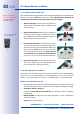
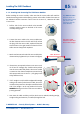
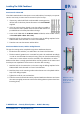
2.2.7 Using MxBus Modules
The MxBus camera connector is located under the housing
cover (clamps 5 and 6 of the screw clamps) and allows the
operation of additional modules for expanding functionality
(e.g. connection of an MX-GPS-Box for determining time
and position). MxBus was optimized specifically for the use
of existing two-wire cables.
The terminal connector has two connectors to connect an
MxBus module (other MxBus modules can then be connected
from there). The length of the entire MxBus cable may not
exceed 50m/55yd.
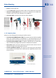
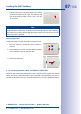
Note
The MxBus wires that are to be stripped at the end should always be fed into the
camera through appropriate plugs before mounting. If
the single wire plug is used, one wire must be pushed
through a hole in the plug.
Do not mix up the polarity of the cables during installa-
tion. Select a consistent cable color for +/- in the entire
MxBus system (for example, red = +, blue = –).
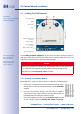
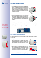
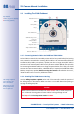
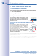
2.2.8 External Audio Support (Microphone/Speaker)
The camera connector for an external microphone and an
external speaker is located under the housing cover (clamps
1 and 2 of the screw clamps for microphone, clamps 3 and
4 for speaker).
An external microphone (red box) and an external speaker
(red box) with the following technical data can be connected
on the terminal connector:
•
Microphone
: V
s
= 2.0 V, R
L
= 2.2 kOhm, sensitivity
–35±4dB, for example, Panasonic Microphone Capsule WM61
•
Speaker
: Max. power output 400mW at 8Ohms impedance, for example, Visaton
Speaker K36WP or K50WP
Mic Speaker MxBus
Mic Speaker MxBus