
Technical data

84/148
S14 Camera Manual: Installation
© MOBOTIX AG • Security Vision Systems • Made in Germany
www.mobotix.com • sales@mobotix.com
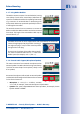
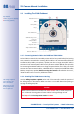
2.3 Installing The S14D FlexMount
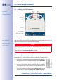
Use the drilling templates supplied (at the end of the manual) to mark the position for
drilling the dowel holes for the camera and the sensor modules. Make sure that it is not
scaled down when printing or copying the drilling template.
Caution
Make sure the camera is mounted on an even surface. If this is not the case, there
is a risk that the housing plate will move and the housing will begin to leak.
The torque for the
housing cover screws
is 0.4Nm.
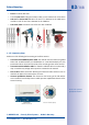
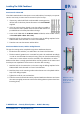
2.3.1 Attaching The S14D Base Module
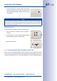
Depending on the system, the base module of a S14D can be installed quickly:
1. If necessary, mark the drill holes at the intended mounting position,
drill the holes for the base plate and hammer in the 6mm dowels
supplied.
2. If this has not been done already, insert the cable tie needed to
ensure that less strain is placed on the connection cable into the slot
provided below in the base plate without closing it.
3.
Screw on the S14D base module using the 4×40mm screws included
(or other suitable screws) and washers (with a diam. of4.3mm).
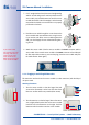
Pressure
compensation
element
Base plate
R L
115mm/4.53in
130mm/5.12in
21
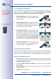
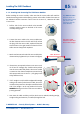
LEDs
MicroSD card
Keys
Triple cable retainer
Bayonet catch
S14D housing cover
Slits for cable ties
LED defaults:
1 Power (on), Error (ashes)
2 Recording (ashes)
The drilling templates
can be found at the
end of the manual
Always print or copy
drilling templates in
their original size