
Technical data

85/148
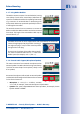
Installing The S14D FlexMount
© MOBOTIX AG • Security Vision Systems • Made in Germany
www.mobotix.com • sales@mobotix.com
2.3.2 Attaching And Connecting The S14D Sensor Modules
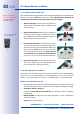
Before installing the sensor modules, make sure that the sensor cables will reach the
intended mounting position without placing a strain on the cables. Further information on
the individual camera connectors can be found in
Section 2.2.1, «Overview Of Cable
Connections».
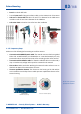
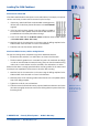
1. Drill the hole for the sensor module at the intended
mounting position (arrow on the back of the sensor
module pointing ”Up”).
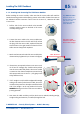
2. Connect the sensor cable to the sensor module (turn
the blue bayonet catch to the left and lift o, remove
the plug, insert the sensor cable, replace the bayonet
catch and turn to the right). Make sure that the sensor
cables are not sharply bent anywhere!
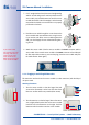
3.
Attach one ferrite at each end of the sensor cable (max.
distance to the plug 10cm/4in, as shown in the figure).
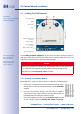
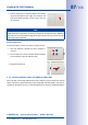
4. If extensions are required (at least one in sensor mod-
ule L11 and 15° wedge), they should now be pushed
over the sensor cable and joined to the sensor module
or extensions that have already been mounted using
the bayonet catch (see
Section 2.3.3, «Plugging In And
Lifting O Extensions»
).
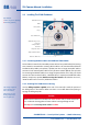
5.
If a 15° wedge is used, the visible wedge and the wedge
sealing must now be pushed onto the cable, the sensor
module and any extensions already mounted (the thicker
side of the wedge is at the top). Make sure that the
MOBOTIX lettering at the front of the sensor module is
pointing upwards!
6. Now insert the cable and then push the whole sensor module (including wedge,
wedge sealing and extension, if installed) through the hole.
Only MOBOTIXcables
should be used to con-
nect the sensor modules
(see
Section 1.10.3,
«Connection Cable For
Sensor Module»
)
Thesensormodule
connectioncablesmust
neverbebentsharply!
Max. 10cm/4in!
M
O
B
O
T
I
X
M
O
B
O
T
I
X
Make sure MOBOTIX
lettering is pointing
upwards!