
Technical data

86/148
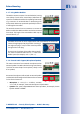
S14 Camera Manual: Installation
© MOBOTIX AG • Security Vision Systems • Made in Germany
www.mobotix.com • sales@mobotix.com
7.
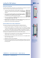
If a 15° wedge has been fitted, the second wedge sealing
and the second wedge must now be pushed over the
sensor cable, any installed extensions and the sensor
module (the thicker side of the wedge is at the bottom)
may need to be shifted to ensure that the nut is properly
positioned on the back.
8. Feed the sensor cable through the nut and secure the
sensor module and mounted extensions using that nut.
If you need to seal o the sensor module against the
wall, you should apply silicone sealant before tighten-
ing the nut.
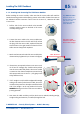
9. Attach the sensor cable of the first sensor module to the Cam1 connector and the
sensor cable of the second sensor module to the Cam2 connector of the S14D (pull
the blue triple cable retainer up, remove the plug, insert the sensor cable and push
the cable retainer down again).
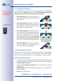
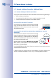
2.3.3 Plugging In And Lifting O Extensions
The extensions are fixed onto the sensor modules (or other extensions) with the help of
a bayonet catch.
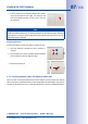
Attaching Extensions
1. Turn the sensor module so that the larger lobe (red
arrow on the illustration) is at the front. The other three
lobes are smaller and do not protrude (blue arrows).
2. Turn the extension so that the larger lobe on the exten-
sion is slightly oset from the lobe on the sensor module
(see blue box in the illustration on the right). Push the
extension with the notches onto the sensor module.
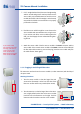
If you install a S14D
with automatic day/night
switching, make sure to
connect the D11 (day)
sensor module on the
Cam1 and the N11 (night)
sensor module on Cam2