
Technical data

88/148
S14 Camera Manual: Installation
© MOBOTIX AG • Security Vision Systems • Made in Germany
www.mobotix.com • sales@mobotix.com
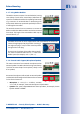
2.4 Installing The S14M FlexMount
2.4.1 Connecting Network Cables And Additional S14M Cables
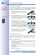
As the S14M is mounted in the intended position with the front panel behind, the housing
cover cannot be removed after mounting. All the cables to be connected there (Ethernet
installation cable, MxBus, microphone, speaker) are then no longer accessible and the
connector for the network patch cable can only be accessed with diculty. The triple lock
for connecting the MiniUSB cable can no longer be opened either. This is why you should
connect the camera network cables, a MiniUSB cable, if required, and additional cables
(MxBus, microphone, speaker)
before mounting the camera
as described in
Section 2.5,
«Network And Power Connection, Additional Cables»
.
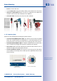
2.4.2 Attaching The S14M Camera Housing
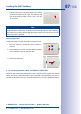
Use the drilling template supplied (at the end of this manual) to mark the position of
the drilling holes for the camera. Make sure that it is not scaled down when printing or
copying the drilling template.
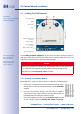
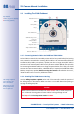
Caution
Make sure the camera is mounted on an even surface. If this is not the case, there
is a risk that the housing plate will move and the housing will begin to leak.
The torque for the
housing cover screws
is 0.4Nm.
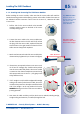
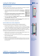
115mm/4.53in
Slits for cable ties
Pressure
compensation
element
Lens with dome
Base plate
R L
130mm/5.12in
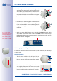
21
LEDs
MicroSD card
Keys
Triple cable retainer
Bayonet catch
S14M housing cover
LED defaults:
1 Power (on), Error (ashes)
2 Recording (ashes)
The drilling templates
can be found at the
end of the manual
Always print or copy
drilling templates in
their original size