
Technical data

91/148
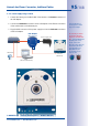
Network And Power Connection, Additional Cables
© MOBOTIX AG • Security Vision Systems • Made in Germany
www.mobotix.com • sales@mobotix.com
2.5.2 Network Cabling For S14 With Patch Cables
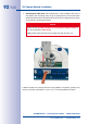
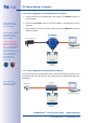
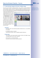
1.
Remove housing cover and cable
plugs
: Loosen the Allen screw on
the housing cover of the S14 and
remove it. Push the cable plug
in the camera out of the hous-
ing from the inside to the outside
(red arrow).
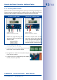
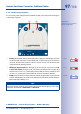
2.
Attach the cable ties
: Feed one
of the cable ties supplied through
both slots in the circuit board
underneath the LSA cutting clamp.
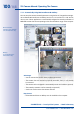
3.
Prepare the installation cable
:
Cut the installation cable to
length, feed through the white
single wire plug (5-7mm/0.2 to
0.28in), remove 35mm/1.38in of
insulation and separate into indi-
vidual twisted wire pairs including
15mm/0.6 in sheathing. Wind the
shield mesh around the sheath to
a width of 10mm/0.4in so that it
can be fixed on the contact surface
later using the cable tie.
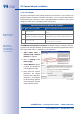
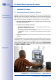
4.
Secure the cable
: Push the
plug out and insert the installa-
tion cable with single wire plug
(5-7 mm/0.2 to 0.28in) into the
opening intended for the instal-
lation cable. The rubber sleeve
must sit tightly on the installation
cable to prevent the penetration
of moisture. Tighten the cable tie
around the shield mesh to ensure
less tension.
~15mm
~35mm
~20mm
~10mm
Shield meshCable
sheath
Wire shield
Ensure that the instal-
lation cable is fed right
into the housing when
the camera is in the right
position so that the cable
plug provides optimal
sealing for the housing