CDM-570/570L Installation and Operation Manual CDM-570 - 70/140 MHz Satellite Modem CDM-570L - L-band Satellite Modem Optional IP Module For Firmware Version 1.5.1 or higher (see New in this Release – Section 1.5) IMPORTANT NOTE: The information contained in this document supersedes all previously published information regarding this product. Product specifications are subject to change without prior notice. Part Number MN/CDM570L.
Comtech EF Data is an ISO 9001 Registered Company CDM-570/570L Satellite Modem Installation and Operation Manual Addendum A Subject: Incorporate NMCS Protocol Part Number: MN/CDM570L.AA4 Addendum A October 9, 2006 Special Instructions: This document contains new information for the CDM-570/570L satellite modem installation and operation manual, part number MN/CDM570L.IOM Rev. 4 dated April 12, 2006. Notes: 1.
Collating Instructions To update the manual, remove and insert the pages as follows: Remove Insert Remote Control Section
CDM/CDD NMCS Protocol Rev 1.0 Revision History Date October 4, 2004 3/01/05 6/27/05 11/10/2005 Rev Draft 1.0 Draft 1.1 Rev 1.0 Rev 1.0 Author Wallace Davis Bryan Wilcutt Bryan Wilcutt Harish Talanki Comments Created for Internal Distribution Modifications for implementation Released revision Modifications Copyright © 2006, Comtech EF Data Comtech EF Data All Rights Reserved.
CDM570/570L Satellite Modem Incorporate NMCS Protocol MN/CDM570L.
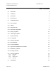
CDM570/570L Satellite Modem Incorporate NMCS Protocol MN/CDM570L.AA4 Table of Contents 1.0 Introduction 4 2.0 Architecture 4 3.0 Introduction 5 3.2 Basic Protocol 5 3.3 Command Structure 6 3.3.1 Start Of Packet 7 3.3.2 Address 7 3.3.3 Instruction Code 7 3.3.4 Instruction Code Qualifier 8 3.3.5 Message Arguments 10 3.3.6 Table Support Qualifier 10 3.4 Modem Commands 11 3.4.1 IP Commands 13 3.4.2 Interface Commands 21 3.4.3 QoS Commands 23 3.4.
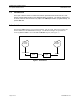
CDM570/570L Satellite Modem Incorporate NMCS Protocol 1.0 MN/CDM570L.AA4 Introduction The scope of this document is to define the interface specification that will be used for a new Remote Control based interface to the CDM/CDD family of products. The primary interface is to be Telnet, however other interfaces may adapt to the CIM implementation, programmatically, via specific API calls. 2.
CDM570/570L Satellite Modem Incorporate NMCS Protocol MN/CDM570L.AA4 NMCS Protocol 3.0 Introduction The following sections outline the basic command set supported in this version of the CIM NMCS protocol. 3.1 Telnet interface Telnet interface into the NMCS system must be on port 7023, which has been reserved for this protocol by the IANA. The login process requires a name and password, which are defined by the systems administrator of the controlling equipment.
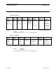
CDM570/570L Satellite Modem Incorporate NMCS Protocol 3.3 MN/CDM570L.AA4 Command Structure Controller-to-target: Start of Packet < ASCII code 60 (1 character) Target Address 1 to 4 chars Address De-limiter / ASCII code 47 (1 character) Instruction Code (3 characters) Row Index (Optional) 1 to 3 characters contained within [ and ] brackets. Code Qualifier = or ? ASCII code 61 or 63 (1 character) Optional Arguments (n characters) End of Packet Carriage Return And Line Feed.
CDM570/570L Satellite Modem Incorporate NMCS Protocol MN/CDM570L.AA4 3.3.1 Start Of Packet Controller to Target: This is the character ‘<’ (ASCII code 60) Target to Controller: This is the character ‘>’ (ASCII code 62) Because this is used to provide a reliable indication of the start of packet, these two characters may not appear anywhere else within the body of the message. For multi line text message, each line should end with a new line character ‘\n’.
CDM570/570L Satellite Modem Incorporate NMCS Protocol MN/CDM570L.AA4 3.3.4 Instruction Code Qualifier This is a single character that further qualifies the preceding instruction code. Code Qualifiers obey the following rules: 3.3.4.
CDM570/570L Satellite Modem Incorporate NMCS Protocol 3.3.4.2 MN/CDM570L.AA4 Target to Controller The only permitted values are: = (ASCII code 61) ! (ASCII code 33) = Code The = code (target to controller) is used in two ways: First, if the controller has sent a query code to a target (for example TFQ?, meaning ‘what’s the Transmit frequency?’), the target would respond with TFQ=xxxx.xxxx, where xxxx.xxxx represents the frequency in question.
CDM570/570L Satellite Modem Incorporate NMCS Protocol MN/CDM570L.AA4 3.3.5 Message Arguments Arguments are not required for all messages. Arguments include ASCII codes for the characters 0 to 9 (ASCII 48 to 57), period (ASCII 46), and | (ASCII 124), plus miscellaneous printable characters. 3.3.6 Table Support Qualifier In order to support accessing information that is represented in a table, the following syntax is supported. 3.3.6.
CDM570/570L Satellite Modem Incorporate NMCS Protocol 3.3.6.2 MN/CDM570L.AA4 Argument lists In order to enforce atomic reads and writes and well as allow for checking related parameter for validity, multi-argument lists will have the following format: • • Arguments are positioned in fixed length format (see specification for each argument) ‘|’ Is used to separate different argument values from each other. 3.3.7 End Of Packet Controller to Target: This is the ‘Carriage Return’ character (ASCII code 13).
CDM570/570L Satellite Modem Incorporate NMCS Protocol MN/CDM570L.
3.4.1 IP Commands 3.4.1.1 Parameter Type System Working Mode Admin Commands Command (Instruction Code and Qualifier) Arguments for Command or Response to Query SWM= 1 byte, value of 0 through 1 EasyConnect Multicast Option EMO= 1 byte, value of 0 or 1 Header Compression Refresh rate – UDP/RTP1 HRR= 3 bytes Description of Arguments Command or Query here: 1 -- Router - Small Network 2 -- Router - Large Network 3 -- Router - Point to Point 4 -- Router - Vipersat 5 -- Easy Connect.
Parameter Type Header Compression Refresh rate – UDP Command (Instruction Code and Qualifier) Arguments for Command or Response to Query HRU= 3 bytes Description of Arguments Command or Query.
Command (Instruction Code and Qualifier) Arguments for Command or Response to Query Administrator Password ADP= 11 bytes No spaces allowed. Command or Query. Change the administrator password, where: Example: ADP=comtech ADP = ADP! ADP? ADP =xxxxxxxxxxx (see description of arguments) ReadWrite UserName RWU= 11 bytes No spaces allowed. RWU = RWU! RWU? RWU =xxxxxxxxxxx (see description of arguments) ReadWrite Password RWP= 11 bytes No spaces allowed. Command or Query.
Command (Instruction Code and Qualifier) Arguments for Command or Response to Query IGMP enable/disable IGE= 1 byte, value of 0 or 1 Command or Query where, 0=Disabled 1= Enabled Enables or disables the IGMP feature. IGE = IGE! IGE? IGE =x (see description of arguments) Access List Enforcement ACE= 1 byte, value of 0 or 1 Command or Query where, 0=Disabled 1= Enabled Enables or disabled access list enforcement.
Parameter Type Trasnmit DES enable/disable Command (Instruction Code and Qualifier) Arguments for Command or Response to Query TDE= 1 byte, value of 0, 1, 2 or 3 Description of Arguments Command or Query where, 0=Disabled 1= Enabled (EasyConnect Only mode) 2= PerRoute (read-only when FAST feature is purchased in router mode) 3 = Unavailable (read-only when FAST feature not purchased) Acts as command, only in EasyConnect mode. In router mode, it’s read-only.
Parameter Type TX Payload Compression enable/disable Command (Instruction Code and Qualifier) Arguments for Command or Response to Query TPE= 1 byte, value of 0, 1, 2 or 3 Description of Arguments Command or Query where, 0=Disabled 1= Enabled (EasyConnect Only mode) 2 = PerRoute (read-only when FAST feature is purchased in router mode) 3 = Unavailable (read-only when FAST feature not purchased) Acts as command, only in EasyConnect mode. In router mode, it’s read-only.
Parameter Type SMTP Domain Name Command (Instruction Code and Qualifier) Arguments for Command or Response to Query SDM= 128 bytes, characters, no spaces Description of Arguments Command or Query. SMTP Domain name of up to 128 characters. To delete the domain name, issue <1/SDM= Empty string will delete the domain name. Response to Command Query (Instruction Code and Qualifier) Response to Query SDM = SDM! SDM? SDM =x [1..128] (see description of arguments) SDN = SDN! SDN? SDN =x [1..
Parameter Type SNMP Trap Destination IP Address-2 Command (Instruction Code and Qualifier) Arguments for Command or Response to Query STB= 15 bytes, Numerical Description of Arguments Command or Query. Used to set the IP address of the SNMP Trap destination IP Address where traps will be sent, in the format: xxx.xxx.xxx.xxx is the IP addresss Response to Command Query (Instruction Code and Qualifier) Response to Query STB = STB! STB? STB = xx.xxx.xxx.
Command (Instruction Code and Qualifier) Arguments for Command or Response to Query Enable/Disable QoS Feature QSE= 1 byte value 0 – Disable 1 – Enable Command or Query. Setting this to ‘1’ enables the Quality of Service feature. Setting to ‘0’ disables it. QSE= QSE! QSE? QSE=x System Configuration Get None String of Variable byte size Query only. Querying the SCG? Dumps the system configuration. This can be used for updating the GUI parameters.
Parameter Type IP Address of Ethernet interface Command (Instruction Code and Qualifier) Arguments for Command or Response to Query IPA= 15 bytes length. Description of Arguments Command or Query. Used to set the IP address and mask of the Ethernet interface, in the format: xxx.xxx.xxx.xxx where xxx.xxx.xxx.xxx is the IP addresss Example: 010.006.030.001 Response to Command Query (Instruction Code and Qualifier) Response to Query IPA = IPA! IPA? IPA= xxx.xxx.xxx.
3.4.3 QoS Commands Command (Instruction Code and Qualifier) Arguments for Command or Response to Query QoS mode QSM= 1 byte, value of 1, 2 or 3. Command or Query. QoS operating mode, where: 1=Priority/Max 2=Min/Max 3=DiffServ Example: <1/QSM=2 QSM = QSM! QSM? QSM =x (see description of arguments) DiffServ Rule DSR= 48 bytes, numerical Command: The value in this is broken into separate values: DSR= DSR! DSR? DSR =x [1..
Parameter Type DiffServ Table Get Command (Instruction Code and Qualifier) Arguments for Command or Response to Query DTG? String of DiffServ Table Description of Arguments Query only. Displays the complete diffserv rules. Can be issued when QoS mode is set in Diff Serv. There are 12-rows/rules. Each rule is separated by chr(13).
Parameter Type Qos Rule Command (Instruction Code and Qualifier) Arguments for Command or Response to Query QSR= QSR[0..32]= Index-0 is the default rule Description of Arguments Command or Query. QSR=tt|p|sss.sss.sss.sss/ss|ddd.ddd.ddd.
Parameter Type Number of QOS Rule entries Command (Instruction Code and Qualifier) Arguments for Command or Response to Query QSN QSN=2 bytes numerical Description of Arguments Query Only. Response to Command Query (Instruction Code and Qualifier) Response to Query QSN = QSN? QSN? QSN = xxx (see description of arguments) QSD = QSD! N/A QSD = xx (see description of arguments) QTL = QTL! QTL? QTL=x X – A value of 0-5 Seconds. QML = QML! QML? QML=x X – A value of 0-5000 milli Seconds.
3.4.4 Protocol Commands Command (Instruction Code and Qualifier) Arguments for Command or Response to Query DHCP Relay IP Address DRA= 15 bytes, numerical Command or Query. Used to set the IP address of the DHCP Server, in the format: xxx.xxx.xxx.xxx, where: xxx.xxx.xxx.xxx is the IP address Example: <1/DRA=010.006.030.001 Returns >0001/DRA=0.0.0.0 when not configured. DRA = DRA! DRA? DRA = xxx.xxx.xxx.
Parameter Type Delete an ARP entry Command (Instruction Code and Qualifier) Arguments for Command or Response to Query ARD= ARD=xxx.xxx .xxx.xxx Description of Arguments Command Only. Delete the ARP entry associated with the specified IP Address. xxx.xxx.xxx.xxx IP address of ARP entry to delete. Response to Command Query (Instruction Code and Qualifier) Response to Query ARD = ARD! N/A ARD=xxx.xxx.xxx.xxx (see description of arguments) Example: <1/ARD=192.168.001.
Command (Instruction Code and Qualifier) Arguments for Command or Response to Query IGMP Client: Version ICV 1 byte, 0 or 1 Command or Query where, Set the IGMP Version for Unsolicited Reports. 0=V1 1= V2 Recognize IGMP Queries Example: ICV =0 ICV = ICV! ICV? ICV =xxx (see description of arguments) IGMP Client: Unsolicated Report Internval IRI= 2 bytes 0..25 Command or Query where, Set the unsolicited Report Interval [Modem as Client] Range = 1..
3.4.6 Operations and Maintenance Commands Parameter Type Upgrade Slot Command (Instruction Code and Qualifier) Arguments for Command or Response to Query USI= 1 bytes, value of 0,1 or 2 Description of Arguments Command or Query. Slot to upgrade new IP firmware where, Response to Command Query (Instruction Code and Qualifier) Response to Query USI = USI! USI? USI=x (see description of arguments) SWR! SWR? SWR=Boot:x.y.zz Bulk1:x.y.zz Bulk2:x.y.
Parameter Type IP Software Information Command (Instruction Code and Qualifier) Arguments for Command or Response to Query None String Description of Arguments Query only. Complete IP software information: Response to Command Query (Instruction Code and Qualifier) IFW! IFW? Response to Query IFW =x….
Parameter Type Boot From Software Image Command (Instruction Code and Qualifier) BLI= Arguments for Command or Response to Query 1 byte, value of 0,1,2 Description of Arguments Command or Query.
Parameter Type Command (Instruction Code and Qualifier) Arguments for Command or Response to Query Description of Arguments Response to Command Query (Instruction Code and Qualifier) Response to Query Reset Unit RST 1 byte value. 1 - reset the system. Command only. Setting the parameter to 1 resets the system. Telnet2 connection needs to be re-established. RST= RST! N/A RST=x (see description of arguments) Restore Factory Defaults RFD 1-Byte value 1 - restore Command only.
3.4.7 Redundancy Commands Parameter Type Redundancy State Command (Instruction Code and Qualifier) Arguments for Command or Response to Query N/A 1 byte, value of 0 or 1 Description of Arguments Query only. Unit returns the redundancy state of the unit, where 0=Offline 1=Online Response to Command N/A Query (Instruction Code and Qualifier) RED? Response to Query RED=x (see description of arguments) Example: RED=1 (which is Online) Page 14 of 54 MN/CDM570L.
3.4.8 Routing Commands Parameter Type Route Table Command (Instruction Code and Qualifier) Arguments for Command or Response to Query RTE RTE[1..256]= variable Description of Arguments Command or Query. sssssssssssss|ddd.ddd.ddd.ddd/DD|i|nnn.nnn.nnn.nnn|hhhh|t|p|c|k|S s = Route Name up to 13 characters. It should be unique. Reusing of route names with different index, will endup modifying the existing route. d = Destination IP Address in xxx.xxx.xxx.xxx/yy where xxx.xxx.xxx.
Parameter Type Command (Instruction Code and Qualifier) Route Table (Continued) Arguments for Command or Response to Query Description of Arguments Response to Command Query (Instruction Code and Qualifier) Response to Query When called using an existing index, the command is treated as a “modify”. Only new routes can be added at the END of the list: Example: RTN? RTN=3 <1/rte[3]= rt3|239.111.102.222.32|0|192.168.001.022|00AB|0|0|1|5|3 Sat Directed Route: >0001/RTE[1]=rt1|011.012.013.014/32|1|***.
Parameter Type Number of route entries Command (Instruction Code and Qualifier) Arguments for Command or Response to Query N/A RTN=3 bytes, numerical Description of Arguments Query Only. Response to Command Query (Instruction Code and Qualifier) RTN = RTN! RTN? RTN = xxxx (see description of arguments) RTD = RTD! RTD = xx.xx RCG? (see description of arguments) RCG= xxxxxxxxxxxxxx xxxxxxxxxxxxxx Returns the number of route entries in the route table.
3.4.9 Statistics Commands 3.4.9.1 Parameter Type WAN TX: Statistics Wan Stats Command (Instruction Code and Qualifier) Arguments for Command or Response to Query None 10 bytes, Numerical Description of Arguments Query only. Display all WAN Transmit Statistics.
Parameter Type WAN RX: Statistics Command (Instruction Code and Qualifier) Arguments for Command or Response to Query None 10 bytes, Numerical Description of Arguments Query only. Display all WAN Receive Statistics. Response to Command Query (Instruction Code and Qualifier) SRT! SRT? Response to Query Text display of all WAN/Satellite Transmit Statistics.
3.4.9.2 Parameter Type IP Route Stats IP Stats Command (Instruction Code and Qualifier) Arguments for Command or Response to Query N/A 10 bytes, Numericals Description of Arguments Query only. Display all IP Route packet statistics in text. Response to Command Query (Instruction Code and Qualifier) IPS! IPS? Response to Query Text display of all IP Route Stats.
Parameter Type IP Filtered Stats Command (Instruction Code and Qualifier) Arguments for Command or Response to Query None 10 bytes, Numerical Description of Arguments Query only. Display all IP Route Filtered packet statistics in text Response to Command Query (Instruction Code and Qualifier) IFT! IFT? Response to Query Text display of all IP Filtered stats.
Parameter Type IP Dropped Statistics Command (Instruction Code and Qualifier) Arguments for Command or Response to Query None 10bytes numerical values Description of Arguments Query only. Display all the IP Route Dropped Packet Statistics in text. Response to Command Query (Instruction Code and Qualifier) IDT! IDT? Response to Query Text display of all IP Dropped stats.
3.4.9.3 Parameter Type Ethernet Rx Statistics Ethernet Stats Command (Instruction Code and Qualifier) None Arguments for Command or Response to Query 10 bytes, Numericals Description of Arguments Query only. Display all the Ethernet Receive statistics in text.
Parameter Type Clear Ether net Stats Command (Instruction Code and Qualifier) ESC=1 Page 14 of 54 Arguments for Command or Response to Query 1byte number. 1 – Clear stats Description of Arguments Set only. Setting this value to ‘1’ clears all the Ethernet Receive & Transmit statistics. Response to Command ESC= ESC! Query (Instruction Code and Qualifier) ESC? Response to Query ESC! MN/CDM570L.
3.4.9.4 Parameter Type Quality of Service Statistics Get QoS Stats Command (Instruction Code and Qualifier) Arguments for Command or Response to Query N/A String of QoS Stats Description of Arguments Query only. Response to Command Query (Instruction Code and Qualifier) QST! QST? Displays the QoS queue statistics of all active queues.
3.5 PARAM Files This section gives more detail about the possible values of various parameters in PARAM file.
Param File Tag Values Associated with Parameter Rt#0 …. Rt#nnn Route table entries Rt#0 is the first entry and can go upto 256 entries. [No need to read this from param file, use RTG] ROUTE_HDLC_ADDR_SAVE Corresponding HDLC Addresses for EthernetÆSat entries. [No need to read this from param file, use RTG] DHCP_RELAY_IP_ADDR DHCP Server IP Address. Possible values are NOT-DEFINED – When the parameter not set. 10.20.30.40 – When a DHCP Server IP Address is set.
Param File Tag Values Associated with Parameter ACCESS_CLIENT NOT-DEFINED/NA – When not set Valid IP address like 192.168.001.001/32 ACCESS_ENFORCEMENT_ENABLE Enabled Disabled PING_REPLY_ENABLE Enabled Disabled TELNETD_ENABLE Enabled Disabled SNMP_ENABLE Enabled Disabled IGMP_ENABLE Unavailable – If system does not has this FAST Feature available. Enabled Disabled GENERIC_DOWNLINK_MCAST Enabled Disabled QOS_ENABLE Unavailable – If system does not has this FAST Feature available.
Param File Tag Values Associated with Parameter RX_HDR_COMPRESSION_ENABLE Unavailable – If system does not has this FAST Feature available. Enabled Disabled TX_PYLDCOMP_ENABLE Unavailable – If system does not has this FAST Feature available. Per Route – If the system working mode is Router-Small, Router-Large, Router-PtoP Enabled – If system working mode is EasyConnect Disabled – If system working mode is EasyConnect ENCRYPT_KEY# [0…7] xxxxx….xx A 48 character length [192-Bit] 3xDES key.
Param File Tag Values Associated with Parameter SNMP_TRAP_DEST NOT-DEFINED – When the parameter is not set IP address in string format like 11.12.13.14 SNMP_TRAP_DEST_2 NOT-DEFINED – When the parameter is not set IP address in string format like 11.12.13.14 SNMP_TRAP_VERSION SNMPv1 – When SNMP version-1 trap generation is selected. SNMPv2 – When SNMP version-2 trap generation is selected. SNMP_TRAP_ENABLE_AUTHEN_TRAP UNKNOWN – When invalid value is set.
Param File Tag Values Associated with Parameter HDLC_ADDR_MODE Small Network Mode Large Network Mode Point-To-Point Mode QOSC QOSCDEFR DIFFSSV#0 … DIFFSSV#11 If there are no QoS rules configured, (or) system is not in Max-Pri (or) Min-Max mode, then param file will not have an entry for QOSC. Otherwise, the rules will be in the following format. QOSC### = SrcIP/Mask DstIP/Mask PROT spm spM dpm dpM mxB mb P W F QOSC#1 = ***/* ***/* RTP *** *** *** *** 22222 0 4 NY QOSC#2 = 11.12.13.14/32 22.22.33.
Param File Tag Values Associated with Parameter IGMP_ROUTERALERT_OPT Possible string values are Yes No IGMP_VERSION2 Possible string values are V1 V2 IGMP_URI A decimal value of 0…25 SARP#0 …. SARP#255 Static ARP entry if there are any, in the format IP Addr Layer2 MAC Address [Hexadecimal digits] 10.20.30.40 00:11:33:AA:BB:CC MGC_SAVE MGC Command response from the base modem. See the base modem document for more detail. OGC_SAVE OGC Command response from the base modem.
Errata A Comtech EF Data Documentation Update Subject: Front Panel Operation – Change Values for CDM-570L Date: Document: July 12, 2006 CDM-570/570L Satellite Modem with Optional IP Module, Installation and Operation Manual, Rev. 4, dated April 12, 2006 MN/CDM-570L.
Filename: T_ERRATA 2
Errata B Comtech EF Data Documentation Update Subject: Serial Remote Control - Unit Alarm Mask Date: Document: July 12, 2006 CDM-570/570L Satellite Modem with Optional IP Module, Installation and Operation Manual, Rev. 4, dated April 12, 2006 MN/CDM-570L.
Unit Alarm Mask MSK= 12 bytes Command or Query. Alarm mask conditions, provides response of 0 (unmasked/active) or 1 (masked) for each parameter, in form abcdefghijkl, where: a=Tx FIFO b=G.
Errata C Comtech EF Data Documentation Update Subject: Serial Remote Control - Front Panel Lockout Date: Document: July 12, 2006 CDM-570/570L Satellite Modem with Optional IP Module, Installation and Operation Manual, Rev. 4, dated April 12, 2006 MN/CDM-570L.
Front Panel Lockout FPL= 1 byte, value of 0 or 1 Command or Query.
Errata D Comtech EF Data Documentation Update Subject: Changed Input Power Range Date: Document: July 18, 2006 CDM-570/570L Satellite Modem with Optional IP Module, Installation and Operation Manual, Rev. 4, dated April 12, 2006 MN/CDM-570L.ED4 Attach this page to page 12-3 Part Number: Collating Instructions: Comments: Highlighted Input Power Range changes are as follows: Change Specifics: 12.2 Demodulator Data rate range, operating modes, de-scrambling, input impedance/return loss etc.
Filename: T_ERRATA 2
Errata E Comtech EF Data Documentation Update Subject: Changed Figure 7-5, TPC Curve for Rate 7/8 Date: Document: July 27, 2006 CDM-570/570L Satellite Modem with Optional IP Module, Installation and Operation Manual, Rev. 4, dated April 12, 2006 MN/CDM-570L.EE4 Attach this page to page 7-14 Part Number: Collating Instructions: Comments: Chnaged slope of curves for TPC 7/8 for Figure 7-5. The following table highlights the changes to the BER curve.
Eb/No in dB 1 2 3 4 5 6 7 8 9 10 11 12 1E-1 Comtech Turbo Product Codec Rate 7/8 QPSK/OQPSK, 8-PSK and 16-QAM Uncoded BPSK/QPSK 1E-2 Uncoded 16-QAM 1E-3 Spec limit Rate 7/8 8-PSK Spec limit Rate 7/8 QPSK/OQPSK Uncoded 8-PSK 1E-4 1E-5 1E-6 1E-7 Spec limit Rate 7/8 16-QAM 1E-8 Typical performance 1E-9 BER 1 2 3 4 5 6 7 8 9 10 Figure 7-5.
Errata F Comtech EF Data Documentation Update Subject: Revised AUPC Parameters in Remote Control Date: Document: October 26, 2006 CDM-570/570L Satellite Modem with Optional IP Module, Installation and Operation Manual, Rev. 4, dated April 12, 2006 MN/CDM-570L.EF4 Attach this page to page 6-17 Part Number: Collating Instructions: Comments: The following changes affects the values shown on page 6-17 and 13-10.
Filename: T_ERRATA 2
Errata G Comtech EF Data Documentation Update Subject: Revised Serial Remote Commands Date: Document: September 18, 2006 CDM-570/570L Satellite Modem with Optional IP Module, Installation and Operation Manual, Rev. 4, dated April 12, 2006 MN/CDM-570L.EG4 Attach this page to page 13-10 Part Number: Collating Instructions: Comments: Revised APP Added ADJ Added VFW Change Specifics: .
AUPC Parameters Internal 10MHz Reference Adjustment APP= ADJ= 6 bytes 4 bytes, numeric Command or Query. Defines AUPC operating parameters. Has the form abc.cd, where: a=Defines action on max. power condition. (0=do nothing, 1=generate Tx alarm) b=Defines action on remote demod unlock. (0=go to nominal power, 1=go to max power) c.c=target Eb/No value, for remote demod, from 0.0 to 14.9 dB, where numbers above 9.9 use hex representation for the 1 st character, ie 14.9 is coded as E.9.
Errata H Comtech EF Data Documentation Update Subject: Revised Options Table Date: Document: October 26, 2006 CDM-570/570L Satellite Modem with Optional IP Module, Installation and Operation Manual, Rev. 4, dated April 12, 2006 MN/CDM-570L.
Filename: T_ERRATA 2
Errata J Comtech EF Data Documentation Update Subject: Revised EIA530 to V.35 DCE Conversion Cable Date: Document: September 25, 2006 CDM-570/570L Satellite Modem with Optional IP Module, Installation and Operation Manual, Rev. 4, dated April 12, 2006 MN/CDM-570L.EJ4 Attach this page to page A-3 Part Number: Collating Instructions: Comments: Revised EIA530 to V.
MALE 25 PIN D TYPE TX CLOCK A TX CLOCK B 24 11 TX DATA A TX DATA B 2 14 RX CLOCK A RX CLOCK B U W TX CLOCK A TX CLOCK B TWISTED PAIR P S TX DATA A TX DATA B 17 9 TWISTED PAIR V X RX CLOCK A RX CLOCK B RX DATA A RX DATA B 3 16 TWISTED PAIR R T RX DATA A RX DATA B INT TX CLK A INT TX CLK B 15 12 TWISTED PAIR Y AA INT TX CLK A INT TX CLK B RS A CS A 4 5 C D RTS CTS RCVR READY A 8 SIG GROUND 7 F B RLSD SIG GROUND SHIELD 1 A SHIELD DM A 6 E OSR LENGTH = TBD NOTES: 34 PIN
Errata K Comtech EF Data Documentation Update Subject: Revised Table 5-2 Data Interface Connector Pin Assignments Date: Document: October 26, 2006 CDM-570/570L Satellite Modem with Optional IP Module, Installation and Operation Manual, Rev. 4, dated April 12, 2006 MN/CDM-570L.EK4 Attach this page to page 5-2 Part Number: Collating Instructions: Comments: Changed TR A and TR B to DM A and DM B as shown: Change Specifics: Table 0-1.
Filename: T_ERRATA 2
Errata L Comtech EF Data Documentation Update Subject: Revised BUC Reference Date: Document: October 26, 2006 CDM-570/570L Satellite Modem with Optional IP Module, Installation and Operation Manual, Rev. 4, dated April 12, 2006 MN/CDM-570L.EL4 Attach this page to page 12-2 Part Number: Collating Instructions: Comments: Change BUC Reference as highlighted Change Specifics: BUC Reference (10 MHz) Phase Noise Filename: T_ERRATA On center conductor of L-band output connector; 10.0 MHz ± 0.
Filename: T_ERRATA 2
CDM-570/570L Installation and Operation Manual CDM-570 - 70/140 MHz Satellite Modem CDM-570L - L-band Satellite Modem Optional IP Module For Firmware Version 1.5.1 or higher (see New in this Release – Section 1.5) Comtech EF Data is an ISO 9001 Registered Company Part Number MN/CDM570L.IOM Revision 4 April 12, 2006 Copyright © Comtech EF Data, 2006. All rights reserved. Printed in the USA. Comtech EF Data, 2114 West 7th Street, Tempe, Arizona 85281 USA, 480.333.2200, FAX: 480.333.
CDM-570/570L Satellite Modem with Optional IP Module Preface Revision 4 MN/CDM570L.
Table of Contents Preface……………….. ...............................................................................................................xv Customer Service ....................................................................................................................... xv About this Manual ...................................................................................................................... xvi Conventions and References........................................................
CDM-570/570L Satellite Modem with Optional IP Module Preface Chapter 2. Revision 4 MN/CDM570L.IOM INSTALLATION ..................................................................................................2–1 2.1 UNPACKING..................................................................................................................2–1 2.2 MOUNTING....................................................................................................................2–2 2.2.
CDM-570/570L Satellite Modem with Optional IP Module Preface Chapter 6. Revision 4 MN/CDM570L.IOM FRONT PANEL OPERATION ............................................................................6–1 6.1 INTRODUCTION............................................................................................................6–1 6.2 OPENING SCREEN.......................................................................................................6–5 6.3 MAIN SELECT MENU...................................
CDM-570/570L Satellite Modem with Optional IP Module Preface Revision 4 MN/CDM570L.IOM 6.15 TEST ........................................................................................................................6–50 6.16 INFO (INFORMATION) ............................................................................................6–52 6.16.1 (INFO) ALL...........................................................................................................6–52 6.16.
CDM-570/570L Satellite Modem with Optional IP Module Preface Chapter 9. Revision 4 MN/CDM570L.IOM CLOCKING MODES ...........................................................................................9–1 9.1 TRANSMIT CLOCKING .................................................................................................9–1 9.1.1 Internal Clock ..........................................................................................................9–1 9.1.2 Tx Terrestrial..........................
CDM-570/570L Satellite Modem with Optional IP Module Preface Chapter 13. Revision 4 MN/CDM570L.IOM SERIAL REMOTE CONTROL ......................................................................13–1 13.1 INTRODUCTION ......................................................................................................13–1 13.2 RS-485 .....................................................................................................................13–1 13.3 RS-232 .........................................
CDM-570/570L Satellite Modem with Optional IP Module Preface Chapter 16. Revision 4 MN/CDM570L.IOM TYPICAL IP MODULE OPERATIONAL SETUPS ........................................16–1 16.1 OVERVIEW ..............................................................................................................16–1 16.2 MODEM COMPATIBILITY .......................................................................................16–1 16.3 IP MODULE WORKING MODES ....................................................
CDM-570/570L Satellite Modem with Optional IP Module Preface Appendix C. Revision 4 MN/CDM570L.IOM FAST ACTIVATION PROCEDURE................................................................ C–1 C.1 INTRODUCTION........................................................................................................... C–1 C.2 ACTIVATION PROCEDURE......................................................................................... C–1 C.2.1 Serial Number .................................................
CDM-570/570L Satellite Modem with Optional IP Module Preface Appendix G. G.1 G.2 Revision 4 MN/CDM570L.IOM GPS MODE .................................................................................................... G–1 HARDWARE SETUP: ................................................................................................... G–1 REMOTE COMMANDS: ...............................................................................................
CDM-570/570L Satellite Modem with Optional IP Module Preface Revision 4 MN/CDM570L.
CDM-570/570L Satellite Modem with Optional IP Module Preface Revision 4 MN/CDM570L.IOM Figures Figure 1-1. CDM-570/570L ...................................................................................................................... 1–1 Figure 2-1. Installation of the Optional Mounting Bracket........................................................................ 2–3 Figure 4-1. Front Panel .............................................................................................................
CDM-570/570L Satellite Modem with Optional IP Module Preface Revision 4 MN/CDM570L.IOM Tables Table 2-1. Optional Mounting Kit , KT/6228-2.......................................................................................... 2–2 Table 5-1. External Connections.............................................................................................................. 5–1 Table 5-2. Data Interface Connector Pin Assignments............................................................................
Preface Customer Service Contact the Comtech EF Data Customer Support Department for: • Product support or training • Information on upgrading or returning a product • Reporting comments or suggestions concerning manuals A Customer Support representative may be reached at: Comtech EF Data Attention: Customer Support Department 2114 West 7th Street Tempe, Arizona 85281 USA 480.333.2200 (Main Comtech EF Data Number) 480.333.4357 (Customer Support Desk) 480.333.
CDM-570/570L Satellite Modem with Optional IP Module Preface Revision 4 MN/CDM570L.IOM About this Manual This manual provides installation and operation information for the Comtech EF Data CDM-570 and CDM-570L satellite modems with optional IP Module. These two modems are essentially identical in their operation. The CDM-570 operates in the 70/140MHz IF band, whereas the CDM-570L operates at L-band, and includes support for externally connected BUCs and LNBs.
CDM-570/570L Satellite Modem with Optional IP Module Preface Revision 4 MN/CDM570L.IOM Reporting Comments or Suggestions Concerning this Manual Comments and suggestions regarding the content and design of this manual will be appreciated. To submit comments, please contact the Comtech EF Data Technical Publications Department: techpub@comtechefdata.com.
CDM-570/570L Satellite Modem with Optional IP Module Preface Revision 4 MN/CDM570L.IOM Environmental The CDM-570/570L must not be operated in an environment where the unit is exposed to extremes of temperature outside the ambient range 0 to 50°C, precipitation, condensation, or humid atmospheres above 95% RH, altitudes (non-pressurized) greater than 2000 meters, excessive dust or vibration, flammable gases, corrosive or explosive atmospheres.
CDM-570/570L Satellite Modem with Optional IP Module Preface Revision 4 MN/CDM570L.IOM EMC (Electromagnetic Compatibility) In accordance with European Directive 89/336/EEC, the CDM-570/570L Modem has been shown, by independent testing, to comply with the following standards: Emissions: EN 55022 Class B - Limits and methods of measurement of radio interference characteristics of Information Technology Equipment.
CDM-570/570L Satellite Modem with Optional IP Module Preface Revision 4 MN/CDM570L.IOM Warranty Policy This Comtech EF Data product is warranted against defects in material and workmanship for a period of two years from the date of shipment. During the warranty period, Comtech EF Data will, at its option, repair or replace products that prove to be defective. For equipment under warranty, the customer is responsible for freight to Comtech EF Data and all related custom, taxes, tariffs, insurance, etc.
Chapter 1. INTRODUCTION Figure 1-1. CDM-570/570L 1.1 Introduction The CDM-570L is an L-band Satellite Modem, intended for closed network applications. The CDM-570 Satellite Modem is the 70/140 MHz IF version of the same modem. Apart from the IF frequency band, the two modems are essentially identical. • • • • • • • • Variable data rates from 2.4 kbps to 9.98 Mbps, in BPSK, QPSK, Offset QPSK, 8PSK, 8-QAM, and 16-QAM modes are offered.
CDM-570/570L Satellite Modem with Optional IP Module Introduction 1.1.1 Revision 4 MN/CDM570L.IOM EDMAC To facilitate network management for small networks, the CDM-570/570L incorporates EDMAC, (Embedded Distant-end Monitor And Control). In this mode, an additional 5% overhead is combined with the traffic data, (1.6% in Turbo BPSK modes, Turbo Rate 1/2 QPSK/OQPSK, and all data rates greater than 2 Mbps). M&C information is added (transparent to the user), allowing access to the distant-end modem.
CDM-570/570L Satellite Modem with Optional IP Module Introduction 1.1.4 Revision 4 MN/CDM570L.IOM Verification The unit includes many test modes and loopbacks for rapid verification of the correct function of the unit. In particular, the IF loopback permits the user to perform a quick diagnostic test without disturbing external cabling.
CDM-570/570L Satellite Modem with Optional IP Module Introduction Revision 4 MN/CDM570L.IOM The following table shows what other options are available: Option Description and Comments Low Rate Variable Mid-Rate Variable Full Rate Variable Extended Rate Variable 8-PSK/8-QAM 16-QAM RS Codec TPC Codec TPC/LDPC Codec * 100W BPSU 150W BPSU Data rate 2.4 kbps to 512 kbps Data rate 2.4 kbps to 2.048 Mbps Data rate 2.4 kbps to 5.0 Mbps Data rate 2.4 kbps to 9.
CDM-570/570L Satellite Modem with Optional IP Module Introduction Revision 4 MN/CDM570L.IOM With FAST technology, operators have maximum flexibility for enabling functions as they are required. FAST allows an operator to order a modem precisely tailored for the initial application. 1.3.3 Implementation FAST is factory-implemented in the modem at the time of order. Hardware options for basic modems can be ordered and installed either at the factory or in the field.
CDM-570/570L Satellite Modem with Optional IP Module Introduction 1.5 Revision 4 MN/CDM570L.IOM New in this release The following Firmware versions incorporate a number of additional features and enhancements. These include: 1.4.5 Release • Adds GPS Mode to permit a Furuno GP-320B GPS receiver to be connected to a distant-end modem, and for the local end to query, via the EDMAC channel, the output from the GPS receiver. See document “CDM-570 GPS Mode” for operation detail. 1.5.
CDM-570/570L Satellite Modem with Optional IP Module Introduction Revision 4 MN/CDM570L.IOM • Enhancements for IP Module: - Supports Supernetting of IP Addresses. - Supports upgrading Base Modem Firmware through IP Module. Allow FTP through IP Module to identified image (1, 2 or inactive image). - Retains Traffic IP Address across Base Modem Firmware upgrade. • Enhancements for Vipersat support (not applicable for non-Vipersat systems). 1.5.
CDM-570/570L Satellite Modem with Optional IP Module Introduction Revision 4 MN/CDM570L.
Chapter 2. INSTALLATION 2.1 Unpacking Inspect shipping containers for damage. If shipping containers are damaged, keep them until the contents of the shipment have been carefully inspected and checked for normal operation. The modem and manual are packaged in pre-formed, reusable, cardboard cartons containing foam spacing for maximum shipping protection. Do not use any cutting tool that will extend more than 1 inch into the container. This can cause damage to the modem.
CDM-570/570L Satellite Modem with Optional IP Module Installation 2.2 Revision 4 MN/CDM570L.IOM Mounting If the CDM-570/570L is to be mounted in a rack, ensure that there is adequate clearance for ventilation, particularly at the sides. In rack systems where there is high heat dissipation, forced air cooling must be provided by top or bottom mounted fans or blowers. Under no circumstance should the highest internal rack temperature be allowed to exceed 50°C (122°F). IMPORTANT 2.2.
CDM-570/570L Satellite Modem with Optional IP Module Installation Revision 4 MN/CDM570L.IOM Equipment Rack Mounting Rail #10 Shoulder Screw #10 Flat W asher BRACKET BOLTS Support Bracket #10 Flat W asher #10 Split W asher #10 Hex Nut Back of Modem Figure 2-1.
CDM-570/570L Satellite Modem with Optional IP Module Installation 2.3 Revision 4 MN/CDM570L.IOM Configuration There are no internal jumpers to configure, no interface cards to install, and no other options to install. All configurations are carried out entirely in software. The unit should first be configured locally, using the front panel keypad and display. The unit will ship with a default 64 kbps, QPSK, Rate 1/2 configuration.
Chapter 3. FUNCTIONAL DESCRIPTION The CDM-570/570L has two fundamentally different types of interface - IF and data. • • The data interface is a bi-directional path, which connects with the customer’s equipment (assumed to be the DTE) and the modem (assumed to be the DCE). The IF interface provides a bi-directional link with the satellite via the uplink and downlink equipment.
CDM-570/570L Satellite Modem with Optional IP Module Functional Description Revision 4 MN/CDM570L.IOM Following this, the data passes to the Plesiochronous/Doppler buffer, which has a programmable size, or may be bypassed. From here, the receive clock and data signals are routed to the terrestrial interface, and are passed to the externally connected DTE equipment.
Chapter 4. PHYSICAL DESCRIPTION 4.1 Introduction The CDM-570/570L is constructed as a 1U high rack-mounting chassis, which can be free-standing, if desired. Rack handles at the front facilitate removal from and placement into a rack. Figure 4-1 shows the front panel of the modem. Figure 4-1. Front Panel 4.2 Front Panel On the front panel of the unit is the Vacuum Fluorescent Display (VFD), keypad, and eight LED indicators. The user enters data via the keypad, and messages are displayed on the VFD.
CDM-570/570L Satellite Modem with Optional IP Module Physical Description Revision 4 MN/CDM570L.IOM The keypad comprises six individual keyswitches, mounted directly behind a fully sealed membrane overlay. They have a positive ‘click’ action which provides the user with tactile feedback. These six switches are identified as ◄ ► (left, right), ▲▼ (up, down) arrows, ENTER and CLEAR. The functions of these keys are described in the ‘Front Panel Operation’ section. There are eight LEDs on the front panel.
CDM-570/570L Satellite Modem with Optional IP Module Physical Description 4.3.1 Revision 4 MN/CDM570L.IOM IEC Line Input Connector The IEC line input connector contains the ON/OFF switch for the unit. It is also fitted with two fuses, one each for line and neutral connections (or L1, L2, where appropriate). These are contained within the body of the connector, behind a small plastic flap. • • For 230 volt AC operation, use T2.5A, (slow-blow) 20mm fuses. For 115 volt AC operation, use T5.
CDM-570/570L Satellite Modem with Optional IP Module Physical Description 4.3.4 Revision 4 MN/CDM570L.IOM External Reference Connector This is BNC female connector. The signal supplied here by the user is used for phaselocking the internal 10MHz reference oscillator, and can be 1, 2, 5, 10 or 20 MHz. The impedance is matched for 50/75Ω, and requires a level in the range –6 to +10 dBm. 4.3.5 Form C Traffic Alarm Connector The Alarms connector is a 15-pin 'D' type male (DB15-M).
CDM-570/570L Satellite Modem with Optional IP Module Physical Description 4.3.10 Revision 4 MN/CDM570L.IOM 10/100 BaseT Ethernet management port connector (M&C) This is a standard RJ45 receptacle for connecting UTP cable to an Ethernet hub, router, switch, PC, etc. Used for upgrading CDM-570L base modem firmware. 4.3.11 10/100 BaseT Ethernet Traffic Port Connector (Traffic, with Optional IP Module) This is a standard RJ45 receptacle for connecting UTP cable to an Ethernet hub, router, switch, PC, etc.
CDM-570/570L Satellite Modem with Optional IP Module Physical Description 4.4 Revision 4 MN/CDM570L.IOM Dimensional Envelope 950 - 1950 MHz 1:N - CAUTION! 100 - 250 volts ~ 50/60 Hz 40 watts, 450 mA max T1.25A fuses for 115 volt ~ T0.75A fuses for 230 volt ~ UNIT STATUS 1.72 inches (44 mm) USB 1.1 STORED EVENT TRANSMIT TRAFFIC REMOTE RECEIVE TRAFFIC EDMAC MODE ON LINE TEST MODE CDM-570L L-BAND SATELLITE MODEM 19.0 inches (480 mm) Figure 4-3.
Chapter 5. CONNECTOR PINOUTS 5.1 Connector Overview The rear panel connectors (Figure 5-1) provide all necessary external connections between the modem and other equipment. Figure 5-1. Rear Panel (shown with optional IP Module Ethernet Interface installed) Table 5-1. External Connections Name Rx IF Tx IF 1:1 Control Data Interface External Reference Remote Control Console 10/100 Ethernet Traffic 10/100 Ethernet M&C Alarms Balanced G.
CDM-570/570L Satellite Modem with Optional IP Module Connector Pinouts 5.2 Revision 4 MN/CDM570L.IOM Data Interface Connector The Data Interface connector, a 25-pin D type female, conducts data input and output breakout panel, or protection switch. Refer to Table 5-2 for pin assignments. THE MODEM IS ALWAYS ASSUMED TO BE DCE. IMPORTANT IMPORTANT Table 5-2.
CDM-570/570L Satellite Modem with Optional IP Module Connector Pinouts 5.3 Revision 4 MN/CDM570L.IOM Balanced G.703 Interface Connector The Balanced G.703 connection is a 15-pin female connector located on the rear panel of the modem. Refer to Table 5-3 for pin assignments. Table 5-3. Balanced G.703 Interface Connector Pin Assignments Pin # 1 9 2 3 11 4 Signal Function Tx G.703 Tx G.703 + Ground Rx G.703 Rx G.703 + Ground Name Tx G.703 In Tx G.703 In GND Rx G.703 Out Rx G.
CDM-570/570L Satellite Modem with Optional IP Module Connector Pinouts 5.5 Revision 4 MN/CDM570L.IOM BNC Connectors There are three BNC connectors located on the rear panel of the modem. Refer to Table 5-5 for pin assignments. Table 5-5. BNC Connectors BNC Connector EXT REF G.703 Out G.703 In 5.6 Description External Reference Input Rx G.703 (Unbalanced) Tx G.703 (Unbalanced) Direction In Out In Unit Alarms Unit alarms are provided on a 15-pin male connector located on the rear panel of the modem.
CDM-570/570L Satellite Modem with Optional IP Module Connector Pinouts 5.7 Revision 4 MN/CDM570L.IOM 1:1 Control Connector The 1:1 Control connection is a 9-pin female connector located on the rear panel of the modem. Refer to Table 5-7 for pin assignments. The 1:1 Control connector is intended only for connection to a CRS-170 Redundancy Switch. Table 5-7. 1:1 Control Interface Connector Pin Assignments Pin # 1 2 3 4 5 6 7 8 9 5.
CDM-570/570L Satellite Modem with Optional IP Module Connector Pinouts 5.9 Revision 4 MN/CDM570L.IOM Ethernet Interface Connectors (Traffic and M&C) The 10/100BaseT Ethernet connector is a RJ45-8 modular jack. There is one connector present on the base modem assembly, used for M&C purposes, and a second connector present if the optional IP module is installed. The second connector is used for the IP traffic connection. This interface is a Network Interface Card (NIC) pinout. Table 5-9.
Chapter 6. FRONT PANEL OPERATION 6.1 INTRODUCTION Figure 6-1. Front Panel View The user can fully control and monitor the operation of the CDM-570/570L from the front panel, using the keypad and display. Nested menus are used, which display all available options, and prompt the user to carry out a required action. The display has two lines each of 24 characters. On most menu screens, the user will observe a flashing solid block cursor, which blinks at a once-per-second rate.
CDM-570/570L Satellite Modem with Optional IP Module Front Panel Operation Revision 4 MN/CDM570L.IOM Table 6-1.
CDM-570/570L Satellite Modem with Optional IP Module Front Panel Operation Revision 4 MN/CDM570L.
CDM-570/570L Satellite Modem with Optional IP Module Front Panel Operation SELECT CONFIGURE MONITOR TEST INFORMATION SAVE/LOAD UTILITY ODU Revision 4 MN/CDM570L.IOM CONFIGURE REMOTE ALL TRANSMIT RECEIVE FRAME INTERFACE REFERENCE ALARM MASKS ODU REMOTE LOCAL SERIAL ETHERNET ADDR GATEWAY ADDRESS MAC SNMP COMMUNITIES TRAPS CONFIGURE ALL (COMPLETE TRANSMIT FEC ENCODER MODULATION CODE RATE DATA RATE FREQUENCY ON/OFF POWER LEVEL SCRAMBLER CLOCKING INVERSION LIVE ALARMS UNIT, RX, TX, RX PARAMETERS EbNo=12.
CDM-570/570L Satellite Modem with Optional IP Module Front Panel Operation 6.2 Revision 4 MN/CDM570L.IOM OPENING SCREEN This screen is displayed whenever power is first applied to the unit. If the Internal Reference warm-up delay feature has been disabled (see under UTIL, REF, Warm-up Delay) on of the following screens is displayed (depending on modem type): Comtech CDM-570L Modem Firmware Version:1.3.1 Comtech CDM-570 Modem Firmware Version:1.3.
CDM-570/570L Satellite Modem with Optional IP Module Front Panel Operation ODU (CDM-570 only) 6.4 Revision 4 MN/CDM570L.IOM (Outdoor Unit). This permits the user to monitor and control a Comtech EF Data RF Transceiver (CSAT or KST-2000A/B), if connected. CONFIG Move the cursor to the desired choice using the ◄ ► arrow keys, then press ENTER.
CDM-570/570L Satellite Modem with Optional IP Module Front Panel Operation 6.5 Revision 4 MN/CDM570L.IOM (CONFIG) REMCONT (Remote control) Select Local, Serial or Ethernet using the ◄ ► arrow keys, then press ENTER. Remote Control: Local Serial Ethernet(◄ ►,ENT) If Local is selected then remote control will be disabled. Remote monitoring is still possible. 6.5.
CDM-570/570L Satellite Modem with Optional IP Module Front Panel Operation Revision 4 MN/CDM570L.IOM changed using the ▲▼ arrow keys. The user should then press ENTER. The valid range of addresses is from 1 to 9999. (CONFIG, REM, SERIAL, BAUD RATE) If the user selects Baud Rate, the user is presented with the following menu: Edit the baud rate of the remote control bus, connected locally to the M&C Local M&C Bus Baud Rate: 19200 Baud (▲ ▼,ENTER) computer. The value is changed using the ▲ ▼ arrow keys.
CDM-570/570L Satellite Modem with Optional IP Module Front Panel Operation Revision 4 MN/CDM570L.IOM (CONFIG, REMOTE, ETHERNET) MAC If MAC is selected, the following information-only sub-menu is displayed: Once the MAC address has been noted, the user should then press ENTER or CLEAR.
CDM-570/570L Satellite Modem with Optional IP Module Front Panel Operation Revision 4 MN/CDM570L.IOM (CONFIG, REMOTE, ETHERNET, SNMP) Traps If Traps is selected, the following sub-menu is displayed: Traps: Community Version IP Addr#1 IP Addr#2 (◄ ►) If Community is selected, the following sub-menu is displayed. Trap Community: (◄ ►,▲ ▼) comtech Edit the SNMP Read or Write Community string using the ◄ ► and ▲ ▼ arrow keys. Only the first 20 characters on the bottom line are available.
CDM-570/570L Satellite Modem with Optional IP Module Front Panel Operation 6.6 Revision 4 MN/CDM570L.IOM (CONFIG) ALL The user is presented, in a sequential fashion, with every configuration option that is part of the individual configuration menus. 6.7 (CONFIG) TX (Transmit) Tx:FEC Mod Code Data Frq On/Off Pwr Scram Clk Inv Select FEC, Mod, Code, Data, Frq, On/Off, Pwr, Scram, Clk or Inv using the ◄ ► arrow keys, then press ENTER. The user will then be taken to a further sub-menu.
CDM-570/570L Satellite Modem with Optional IP Module Front Panel Operation IMPORTANT Revision 4 MN/CDM570L.IOM VERY IMPORTANT NOTE: The FEC type takes the highest configuration priority, and the selection here depends on what, if any, optional plug-in codecs are installed. The choice of FEC type then determines what modulation types, code rates, and data rates are available.
CDM-570/570L Satellite Modem with Optional IP Module Front Panel Operation 6.7.2 Revision 4 MN/CDM570L.IOM (CONFIG, TX) MODULATION Modulation: BPSK QPSK OQPSK 8-PSK 16-QAM 8-QAM IMPORTANT IMPORTANT NOTE: All possible choices are presented at all times. If an option is not installed (either Hardware, or FAST) or valid, the ◄ ► arrow keys will force the cursor to skip past the unavailable choice. CASE BPSK QPSK OQPSK 8-PSK 8-QAM 16-QAM 6.7.
CDM-570/570L Satellite Modem with Optional IP Module Front Panel Operation 6.7.4 Revision 4 MN/CDM570L.IOM (CONFIG, TX) DATA RATE Tx Dat Rate:5000.000kbps 3000.000ksym (◄ ►,▲ ▼,ENT) IMPORTANT The overall range of data rates is from 2.4 to 9980 kbps. The overall range of symbol rates is from 4.8 to 3000 ksymbols/second. The minimum and maximum data rates are dependent on modulation type and FEC encoder rate.
CDM-570/570L Satellite Modem with Optional IP Module Front Panel Operation 6.7.5 Revision 4 MN/CDM570L.IOM (CONFIG, TX) FREQUENCY Tx IF Freq:1156.3456 MHz (◄ ►,▲ ▼,ENT) Edit the Transmit IF Frequency. This is accomplished by selecting the digit to be edited using ◄ ► arrow keys. The value of the digit is then changed using the ▲ ▼ arrow keys. The user should then press ENTER. For the CDM-570L, the range of frequencies is from 950 to 1950 MHz, with a resolution of 100 Hz.
CDM-570/570L Satellite Modem with Optional IP Module Front Panel Operation Revision 4 MN/CDM570L.IOM seconds before the transmit carrier is inhibited. This time interval is fixed and the user cannot change it. IMPORTANT IMPORTANT NOTE: Having this feature enabled does not affect the internal IF loopback feature.
CDM-570/570L Satellite Modem with Optional IP Module Front Panel Operation Revision 4 MN/CDM570L.IOM (CONFIG, TX, PWR, MODE) AUPC Target-Eb/No Max-Range Alarm DemodUnlock (◄ ►) Select either Target EbNo, Max-Range, Alarm or Demod-Unlock using the ◄ ► arrow keys. The user should then press ENTER. (CONFIG, TX, PWR, MODE, AUPC) TARGET EbNo Remote Demod - Target Min Eb/No:9.9dB (◄ ►,▲ ▼) Edit the target Eb/No of the remote demod, using the ◄ ► and ▲ ▼ arrow keys. Default value is 3.
CDM-570/570L Satellite Modem with Optional IP Module Front Panel Operation 6.7.8 Revision 4 MN/CDM570L.
CDM-570/570L Satellite Modem with Optional IP Module Front Panel Operation 6.7.10 Revision 4 MN/CDM570L.IOM (CONFIG, TX) INVERSION FUNCTIONS Tx Inversion functions: Spectrum Data (◄ ►,ENT) Select Spectrum or Data, using the ◄ ► arrow keys, then press ENTER. (CONFIG, TX, INV) SPECTRUM If Spectrum is selected, the following sub-menu will be displayed: Tx Spectrum: Normal Inverted (◄ ►,ENTER) Select Normal or Inverted, using the ◄ ► arrow keys, then press ENTER.
CDM-570/570L Satellite Modem with Optional IP Module Front Panel Operation 6.8 Revision 4 MN/CDM570L.IOM (CONFIG) RX (Receive) The sub-branches available are: Rx:FEC Dem Code Data Frq Acq Descram Buf Inv EbNo Select FEC, Dem, Code, Data, Frq, Acq, Descram, Buf, Inv or EbNo using the ◄ ► arrow keys, then press ENTER. The user will then be taken to a further sub-menu.
CDM-570/570L Satellite Modem with Optional IP Module Front Panel Operation IMPORTANT Revision 4 MN/CDM570L.IOM VERY IMPORTANT NOTE: The FEC type takes the highest configuration priority, and the selection here depends on what, if any, optional plug-in codecs are installed. The choice of FEC type then determines what demodulation types, code rates, and data rates are available.
CDM-570/570L Satellite Modem with Optional IP Module Front Panel Operation 6.8.2 Revision 4 MN/CDM570L.IOM (CONFIG, RX) DEMODULATION Demodulation: BPSK QPSK OQPSK 8-PSK 8-QAM 16-QAM IMPORTANT IMPORTANT NOTE: All possible choices are presented at all times. If an option is not installed (either Hardware, or FAST) or valid, the ◄ ► arrow keys will force the cursor to skip past the unavailable choice. CASE BPSK QPSK OQPSK 8-PSK 8-QAM 16-QAM 6.8.
CDM-570/570L Satellite Modem with Optional IP Module Front Panel Operation 6.8.4 Revision 4 MN/CDM570L.IOM (CONFIG, RX) DATA RATE Rx Dat Rate:5000.000kbps 2500.000ksym (◄ ►,▲ ▼,ENT) IMPORTANT Overall range of data rates is from 2.4 to 9980 kbps. Overall range of symbol rates is 4.8 to 2500 ksymbols/second. Minimum and maximum data rates are dependent on modulation type and FEC encoder rate.
CDM-570/570L Satellite Modem with Optional IP Module Front Panel Operation 6.8.5 Revision 4 MN/CDM570L.IOM (CONFIG, RX) FREQUENCY Rx IF Freq:1156.3456 MHz (◄ ►,▲ ▼,ENT) Edit the receive frequency. This is accomplished by selecting the digit to be edited, using the ◄ ► arrow keys. The value of the digit is then changed using the ▲ ▼ arrow keys. The user should then press ENTER. The range of frequencies is from 950 to 1950 MHz, with a resolution of 100 Hz.
CDM-570/570L Satellite Modem with Optional IP Module Front Panel Operation Revision 4 MN/CDM570L.IOM The value entered here determines the amount of frequency uncertainty the demodulator will search over in order to find and lock to an incoming carrier. In the CDM-570L. the range varies according to symbol rate: +/- 1 kHz to +/- 200 kHz for rates less than or equal to 625 ksymbols/sec +/- 1 kHz to +/- 32 kHz for rates greater than 625 ksymbols/sec In the CDM-570, the range is +/- 1 kHz to +/- 32 kHz.
CDM-570/570L Satellite Modem with Optional IP Module Front Panel Operation 6.8.8 Revision 4 MN/CDM570L.IOM (CONFIG, RX) BUFFER Edit the size, in bits, of the Plesiochronous/Doppler Buffer. The value is changed using the ▲ ▼ arrow keys. The user should then press ENTER. Values of Disabled, +/- 128, 256, 512, 1024, 2048, 4096, 8192, 16384 and 32768 bits are possible. When Disabled is selected, the Plesiochronous/Doppler buffer is disabled.
CDM-570/570L Satellite Modem with Optional IP Module Front Panel Operation Revision 4 MN/CDM570L.IOM If Spectrum is selected, the following sub-menu will be displayed: Rx Spectrum: Normal Inverted (◄ ►,ENTER) Select Normal or Inverted, using the ◄ ► arrow keys, then press ENTER. If Data is selected, the following sub-menu will be displayed: Rx Data Sense: Normal Inverted (◄ ►,ENTER) Select Normal or Inverted, using the ◄ ► arrow keys, then press ENTER. 6.8.10 (CONFIG, RX) Eb/No Eb/No Alarm Point: 02.
CDM-570/570L Satellite Modem with Optional IP Module Front Panel Operation 6.9.1 Revision 4 MN/CDM570L.IOM (CONFIG, FRAME) UNFRAMED No framing is selected. No overhead is added, and the unit will be compatible with other manufacturer’s equipment, when operating in a ‘standard’ configuration. 6.9.2 (CONFIG, FRAME) EDMAC or EDMAC-2 Comtech EF Data’s proprietary framing is added. The framing permits the bi-directional passing of M&C and AUPC data between local and distant-end units.
CDM-570/570L Satellite Modem with Optional IP Module Front Panel Operation Revision 4 MN/CDM570L.IOM Distant-end Base Address 0240 (◄ ►,▲ ▼,ENTER) Edit the address of the distant-end modem to which this unit will pass messages. This is accomplished by selecting the digit to be edited, using the ◄ ► arrow keys. The value of the digit is changed using the ▲ ▼ arrow keys. The user should then press ENTER.
CDM-570/570L Satellite Modem with Optional IP Module Front Panel Operation 6.10 Revision 4 MN/CDM570L.IOM (CONFIG) INTERFACE Select RS422 (EIA-530), IP, V.35, RS232, or G.703 using the ◄ ► arrow keys, then press ENTER Data Interface: RS422 IP V.35 RS232 G.703(◄ ►,ENT) If RS422, V.35, or RS232 are selected, the following sub-menu will be displayed: RTS/CTS Operation: (▲ ▼) Loop,RTS Controls Tx Out The option is changed using the ▲ ▼ arrow keys. The user should then press ENTER.
CDM-570/570L Satellite Modem with Optional IP Module Front Panel Operation Revision 4 MN/CDM570L.IOM Select Length or Line Code using the ◄ ► arrow keys, then press ENTER If Line-Code is selected, the following sub-menu will be displayed: T1 Line Code (B8ZS): On Off(AMI) (◄ ►,ENTER) Select On or Off using the ◄ ► arrow keys, then press ENTER.
CDM-570/570L Satellite Modem with Optional IP Module Front Panel Operation 6.11 IMPORTANT Revision 4 MN/CDM570L.IOM (CONFIG) REFERENCE IMPORTANT NOTE: The CDM-570/570L can accept an externally supplied frequency reference, using the BNC connector on the rear panel.
CDM-570/570L Satellite Modem with Optional IP Module Front Panel Operation 6.12 Revision 4 MN/CDM570L.IOM (CONFIG) MASK Alarm Mask: Transmit Receive Ref BUC LNB (◄ ►) Select Transmit, Receive, Reference, BUC or LNB using the ◄ ► arrow keys, then press ENTER. Note that the BUC and LNB choices are only applicable for the CDM570L. If Transmit is selected the following sub-menu will be displayed: Tx Alarm Mask: Tx-FIFO G.703-BPV Tx-AIS(◄ ►,ENT) Select Tx-FIFO, G.
CDM-570/570L Satellite Modem with Optional IP Module Front Panel Operation Revision 4 MN/CDM570L.IOM If the user selects Active, then a Receive Traffic fault will be generated whenever the demodulator sees that the composite input level being applied will cause compression in the IF stages, and hence degrade the performance of the demodulator. Similarly, the user can mask an Eb/No, Receive AIS or Buffer alarm. If the user selects Masked, no alarm will be generated.
CDM-570/570L Satellite Modem with Optional IP Module Front Panel Operation 6.13 Revision 4 MN/CDM570L.IOM (CONFIG) ODU (CDM-570L ONLY) ODU (Outdoor Unit): BUC LNB (◄ ►,ENTER) In CDM-570L applications, the ODU (Outdoor Unit) menu permits the user to choose between controlling and monitoring either a BUC (Block Upconverter) or an LNB (Lownoise Block downconverter). Select BUC or LNB , using the ◄ ► arrow keys, then press ENTER. 6.13.
CDM-570/570L Satellite Modem with Optional IP Module Front Panel Operation Revision 4 MN/CDM570L.IOM (CONFIG, ODU, BUC) M&C-FSK BUC M&C(FSK): FSK-Comms Address Tx-On/Off (◄ ►) If M&C-FSK is selected, the following sub-menu is displayed: Select Comms, Address, or Tx-On/Off, using the ◄ ► arrow keys, then press ENTER. FSK-Comms Address If an FSK-capable BUC is employed, this menu turns the FSK between the modem and BUC either ON or OFF.
CDM-570/570L Satellite Modem with Optional IP Module Front Panel Operation Revision 4 MN/CDM570L.IOM (CONFIG, ODU, BUC, M&C-FSK) TX-ON/OFF If Tx-On/Off is selected, the following sub-menu is displayed: BUC RF Output: On Off (◄ ►,ENTER) Select On or Off , using the ◄ ► arrow keys, then press ENTER. (CONFIG, ODU, BUC) DC-POWER If DC-Power is selected, the following sub-menu is displayed: BUC DC Power: On Off (◄ ►,ENTER) Select On or Off , using the ◄ ► arrow keys, then press ENTER.
CDM-570/570L Satellite Modem with Optional IP Module Front Panel Operation Revision 4 MN/CDM570L.IOM If Upper is selected, the following sub-menu is displayed: BUC Current Alarm Upper Limit:1200mA (◄ ►,▲ ▼,ENT) Edit BUC Current Alarm Upper limit. This is accomplished by selecting the digit to be edited, using the ◄ ► arrow keys. The value of the digit is then changed using the ▲ ▼ arrow keys. The user should then press ENTER. The range of current is 500 to 4000 mA.
CDM-570/570L Satellite Modem with Optional IP Module Front Panel Operation Revision 4 MN/CDM570L.IOM (CONFIG, ODU, BUC) MIX If Mix is selected, the following sub-menu is displayed: BUC Frequency Mix: High-Side Low-Side (◄ ►) Select High-Side or Low-Side, using the ◄ ► arrow keys, then press ENTER. 6.13.
CDM-570/570L Satellite Modem with Optional IP Module Front Panel Operation Revision 4 MN/CDM570L.IOM (CONFIG, ODU, LNB) 10MHz If 10MHz is selected, the following sub-menu is displayed: LNB 10MHz Reference: On Off (◄ ►,ENTER) Select On or Off , using the ◄ ► arrow keys, then press ENTER. (CONFIG, ODU, LNB) ALARM If Alarm is selected, the following sub-menu is displayed: Set LNB Current Alarm: Upper Lower (◄ ►,ENTER) Select Upper or Lower , using the ◄ ► arrow keys, then press ENTER.
CDM-570/570L Satellite Modem with Optional IP Module Front Panel Operation Revision 4 MN/CDM570L.IOM (CONFIG, ODU, LNB) LO If LO is selected, the following sub-menu is displayed: LNB LO Frequency: 12000 MHz (◄ ►,▲ ▼,ENTER) Edit the value of the LNB LO frequency. This is accomplished by selecting the digit to be edited, using the ◄ ► arrow keys. The value of the digit is then changed using the ▲ ▼ arrow keys. The user should then press ENTER. The valid range is from 3000 to 6 5000 MHz.
CDM-570/570L Satellite Modem with Optional IP Module Front Panel Operation 6.14 Revision 4 MN/CDM570L.IOM MONIT (Monitor) MONITOR:Alarms Rx-Params Event-Log Stats AUPC ODU Select Alarms, Rx-Params, Event-Log, Stats, AUPC or ODU using the ◄ ► arrow keys, then press ENTER. If the user selects Alarms, the following sub-menu is displayed: 6.14.1 (MONIT) ALARMS Live Alarms:Unit Receive Transmit ODU (◄ ►,ENTER) IMPORTANT IMPORTANT NOTE: The CDM-570L uses a system of Fault Prioritization.
CDM-570/570L Satellite Modem with Optional IP Module Front Panel Operation Revision 4 MN/CDM570L.IOM (MON, ALARMS) TRANSMIT (Transmit Traffic Status) Tx Traffic: No Tx Clock from Terrestrial (ENT) The screen will indicate if there are any Transmit Traffic Faults. If not, it will display ‘None’. Pressing ENTER takes the user back to the previous menu. (MON, ALARMS) ODU (Outdoor Unit alarms) ODU Alarms: BUC Current Over Limit (ENT) The screen will indicate if there are any ODU Alarms.
CDM-570/570L Satellite Modem with Optional IP Module Front Panel Operation Revision 4 MN/CDM570L.IOM ODU status: 1) BUC PLL lock fault 2) BUC current out of limits 3) BUC voltage out of limits 4) LNB current out of limits 5) LNB voltage out of limits 6) BUC temperature alarm 7) BUC software checksum error 6.14.2 (MONIT) RX-PARAMS (Receive Parameters) If the user selects Rx-Params, the following sub-menu is displayed: EbNo=05.7dB BER=3.4E-9 ΔF=+11.
CDM-570/570L Satellite Modem with Optional IP Module Front Panel Operation 6.14.3 Revision 4 MN/CDM570L.IOM (MONIT) EVENT-LOG (STORED EVENTS) If the user selects Stored Events, the following sub-menu is displayed: Stored Events: Clear-All View (◄ ►,ENTER) Select View or Clear-All, using the ◄ ► arrow keys, then press ENTER.
CDM-570/570L Satellite Modem with Optional IP Module Front Panel Operation 6.14.4 Revision 4 MN/CDM570L.IOM (MONIT) STATS (Link Statistics) If the user selects Stats, the following sub-menu is displayed: Link Statistics: View Clear-All Config(◄ ►,ENT) Select View, Clear-All or Configure, using the ◄ ► arrow keys, then press ENTER. (MONIT, STATS) VIEW If the user selects View, the following screen is displayed: Sta198:02/11/02 10:37:32 16.0, 16.0, 9.0, 9.
CDM-570/570L Satellite Modem with Optional IP Module Front Panel Operation Revision 4 MN/CDM570L.IOM If the measured values are greater than, or equal to 16.0 dB, the display will show 16.0 dB. If AUPC is not enabled, the values of maximum and average TPLI will both show ‘Off'. Examples: 08.0, 13.5, 2.5, 1.8 means: Minimum Eb/No observed in the measurement interval = 8.0 dB Average Eb/No observed in the measurement interval = 13.5 dB Maximum TPLI observed in the measurement interval = 2.
CDM-570/570L Satellite Modem with Optional IP Module Front Panel Operation 6.14.5 Revision 4 MN/CDM570L.IOM (MONIT) AUPC If the user selects AUPC, and the modem is not in Framed mode, the following submenu is displayed: Framing is required for AUPC Monitor (ENT or CLR) If the user selects AUPC, and the modem is in Framed mode, the following sub-menu is displayed: AUPC:Remote EbNo =14.0dB TX Power Increase =2.
CDM-570/570L Satellite Modem with Optional IP Module Front Panel Operation Revision 4 MN/CDM570L.IOM If BUC is selected, the following menu is displayed: BUC:DC=47.8V,3.25A SW=05 T=+38C PLL=Flt Pwr=02.1W The menu displays the following parameters: DC T SW PLL Pwr (DC Power) If a BUC supply is installed, displays measured BUC supply voltage and load current, measured at the Tx-IF connector. (Temperature) If BUC FSK is enabled, displays BUC ambient temperature in °C.
CDM-570/570L Satellite Modem with Optional IP Module Front Panel Operation 6.15 Revision 4 MN/CDM570L.IOM TEST TEST: Norm IF> Dig> I/O> RF> Tx-CW Tx-1,0(◄ ►,ENT) Select Norm, IF Loop, Dig Loop, I/O Loop, RF Loop, Tx-CW, or Tx-1,0, using the ◄ ► arrow keys, then press ENTER. This sub-menu permits the user to select the following test modes: Norm IF Loop Dig Loop I/O Loop RF Loop TX-CW TX-1,0 (Normal) This clears any test modes or loopbacks, and places the unit back into an operational state.
CDM-570/570L Satellite Modem with Optional IP Module Front Panel Operation IF LOOPBACK DIGITAL LOOPBACK I/O LOOPBACK Figure 6-4. Loopback Modes 6–51 Revision 4 MN/CDM570L.
CDM-570/570L Satellite Modem with Optional IP Module Front Panel Operation 6.16 Revision 4 MN/CDM570L.IOM INFO (Information) INFO:All Tx Rx Buf Frame Intfc Rem Msk Ref ID 1:1 Select All, Tx, Rx, Buf, Frame, Intfc, Rem, Mask, Red, ID or 1:1, using the ◄ ► arrow keys, then press ENTER. These screens display information on the current configuration of the unit. Depending on the choice selected, one of the following screens will be displayed: 6.16.
CDM-570/570L Satellite Modem with Optional IP Module Front Panel Operation 6.16.3 Revision 4 MN/CDM570L.IOM (INFO) RX (Receive information) Rx:1140.000 5000.000 TUR 8P 0.
CDM-570/570L Satellite Modem with Optional IP Module Front Panel Operation 6.16.5 Revision 4 MN/CDM570L.IOM (INFO) FRAME (Framing and EDMAC information) Examples: Framing: Disabled (ENTER or CLEAR) Framing:AUPC-Only,EDMAC2 (ENTER or CLEAR) Framing: AUPC+EDMAC2 Master,0240 (ENT or CLR) Framing: AUPC+EDMAC Slave, 0241 (ENT or CLR) This screen shows EDMAC mode, and shows if the unit is EDMAC Master or Slave, with the appropriate address. Pressing ENTER or CLEAR takes the user back to the previous menu.
CDM-570/570L Satellite Modem with Optional IP Module Front Panel Operation 6.16.7 Revision 4 MN/CDM570L.IOM (INFO) REMCONT (Remote Control information) This screen shows if the unit is in Local or Remote mode, and gives details of the electrical interface type selected, the unit’s address, and the baud rate selected, etc. Pressing ENTER or CLEAR takes the user back to the previous menu.
CDM-570/570L Satellite Modem with Optional IP Module Front Panel Operation 6.16.10 Revision 4 MN/CDM570L.IOM (INFO) ID (Circuit ID) This displays the user-defined Circuit ID string, which is entered via the UTIL, ID screen. To return to the previous menu, press ENTER. Circuit ID: (ENTER) 24 CHARACTER TST MESSAGE 6.16.
CDM-570/570L Satellite Modem with Optional IP Module Front Panel Operation Revision 4 MN/CDM570L.IOM Save Config to Loc: 9 11:10:29 23/12/03 (▲ ▼) The user is shown the time and date stamp of the previously stored configuration, for identification purposes. Select the location where the current configuration will be stored, using the ▲ ▼ arrow keys, then press ENTER. Locations 0 through 9 are available.
CDM-570/570L Satellite Modem with Optional IP Module Front Panel Operation Revision 4 MN/CDM570L.IOM If the selected location contains valid data, the following screen will be displayed: New Config has been Loaded from Loc 9 (ENT) Pressing ENTER or CLEAR will take the user back to the previous menu. 6.18 UTILITY UTIL: Buffer Clock Ref ID 1:1 VFD Firmware FAST Select Buffer, Clock, Ref, ID, 1:1, VFD, Firmware or FAST using the ◄ ► arrow keys, then press ENTER.
CDM-570/570L Satellite Modem with Optional IP Module Front Panel Operation 6.18.3 Revision 4 MN/CDM570L.IOM (UTIL) REF (Reference) Internal Freq Ref:Adjust Warm-up delay (◄ ►,ENTER) Select Adjust or Warm-up delay using the ◄ ► arrow keys, then press ENTER. (UTIL, REF) ADJUST If Adjust is selected, the following sub-menu is displayed: Internal 10 MHz Freq Ref Fine Adjust:+017(◄ ►,▲ ▼) Fine adjustment of the Internal 10 MHz reference oscillator is possible through this menu.
CDM-570/570L Satellite Modem with Optional IP Module Front Panel Operation Revision 4 MN/CDM570L.IOM value. This will affect the Tx synthesizer (and hence the Tx output frequency), the Rx synthesizers, and the generation of the Internal Tx baseband clock. For a CDM-570L operating on its own, this may not be a problem, but if the 10 MHz reference signal is being used to drive an externally-connected BUC, the frequency error at the RF output may be large, particularly at Ku or Ka-band.
CDM-570/570L Satellite Modem with Optional IP Module Front Panel Operation 6.18.4 Revision 4 MN/CDM570L.IOM (UTIL) ID (Circuit ID) Edit Circuit ID:(◄ ►,▲ ▼) 24 CHARACTER TST MESSAGE Edit the Circuit ID string, using the ◄ ► and ▲ ▼ arrow keys. Only the bottom line is available (24 characters). The cursor selects the position on the bottom line (◄ ►) and the character is then edited (▲ ▼). The following characters are available: Space ( ) * + - , . / 0-9 and A-Z.
CDM-570/570L Satellite Modem with Optional IP Module Front Panel Operation 6.18.7 Revision 4 MN/CDM570L.IOM (UTIL) FIRMWARE This series of sub-menus permits the user to view information about the CDM-570/570L internal firmware. The modem can store two complete firmware images, and the user can select which image will be loaded the next time the unit re-boots. IMPORTANT THESE MENUS ARE FOR DIAGNOSTIC PURPOSES. ONLY CHANGE AN IMAGE IF INSTRUCTED TO DO SO BY COMTECH EF DATA CUSTOMER SUPPORT TECHNICIANS.
CDM-570/570L Satellite Modem with Optional IP Module Front Panel Operation 6.18.8 Revision 4 MN/CDM570L.IOM (UTIL) FAST (FAST code options) FAST is the way to enable new options in the modem. Obtain the FAST code for the new option from Comtech EF Data. FAST:Cnfg View (H/W 0.03) MainBoard S/N: 123456789 The FAST menu allows the user to either Configure (enter) a new FAST code into the unit or to enable Demo Mode, or to View which options are currently installed.
CDM-570/570L Satellite Modem with Optional IP Module Front Panel Operation Revision 4 MN/CDM570L.IOM If the user selects Demo Mode, then the following menu is displayed: FAST Demo Mode: Off On 604800 seconds remain Use the ◄ ► arrow keys to move the cursor to select Off or On. When On, the second line will display the number of seconds remaining available for the free Demo Mode. When enabled, Demo Mode allows access to ALL CDM-570/570L FAST options for 604800 seconds (7 full days).
CDM-570/570L Satellite Modem with Optional IP Module Front Panel Operation Option Number 01 02 03 04 05 06 07 08 09 10 11 12 13 14 15 16 17 Option Type Hardware Hardware Hardware Hardware Hardware Hardware Hardware Hardware FAST FAST FAST FAST FAST FAST FAST FAST FAST Revision 4 MN/CDM570L.
CDM-570/570L Satellite Modem with Optional IP Module Front Panel Operation Notes: 6–66 Revision 4 MN/CDM570L.
Chapter 7. FORWARD ERROR CORRECTION OPTIONS 7.1 Introduction As standard, the CDM-570/570L Modem is equipped with an industry-standard Viterbi Forward Error Correction (FEC) encoder/decoder. The constraint lengths and encoding polynomials are compatible with the vast majority of existing modems from other manufacturers. Comtech EF Data has performed compatibility testing to ensure interoperability.
CDM-570/570L Satellite Modem with Optional IP Module Forward Error Correction Options 7.2 Revision 4 MN/CDM570L.IOM Viterbi The combination of convolutional coding and Viterbi decoding has become an almost universal standard for satellite communications. The CDM-570/570L complies with the Intelsat IESS 308/309 standards for Viterbi decoding with a constraint length of seven.
CDM-570/570L Satellite Modem with Optional IP Module Forward Error Correction Options Revision 4 MN/CDM570L.IOM improvements in error performance without significant bandwidth expansion. The coding overhead added by the RS outer Codec is typically around 10%, which translates to a 0.4 dB power penalty for a given link. Reed-Solomon codes are block codes (as opposed to Viterbi which is convolutional), and in order to be processed correctly the data must be framed and de-framed.
CDM-570/570L Satellite Modem with Optional IP Module Forward Error Correction Options 7.4 Revision 4 MN/CDM570L.IOM Trellis Coding (requires 8-PSK/8-QAM FAST Option) In the other FEC methods described here, the processes of coding and modulation are independent. The FEC codec has no knowledge of, or interaction with, the modulator. However, there are schemes in which the coding and modulation are combined together, where the encoder places FEC symbols in a precise manner into the signal constellation.
CDM-570/570L Satellite Modem with Optional IP Module Forward Error Correction Options Revision 4 MN/CDM570L.IOM 7.5 Turbo Product Codec (Hardware Option) 7.5.1 Introduction Turbo coding is an FEC technique developed within the last few years, which delivers significant performance improvements compared to more traditional techniques. Two general classes of Turbo Codes have been developed, Turbo Convolutional Codes (TCC), and Turbo Product Codes (TPC, a block coding technique).
CDM-570/570L Satellite Modem with Optional IP Module Forward Error Correction Options 7.5.3 Revision 4 MN/CDM570L.IOM 8-QAM Modulation What is 8-QAM, and why is it important? Unlike 8-PSK, which comprises 8 equally spaced constellation points around a unit-circle, 8-QAM is comprised of exactly half of a 16-QAM signal.
CDM-570/570L Satellite Modem with Optional IP Module Forward Error Correction Options 7.5.5 Revision 4 MN/CDM570L.IOM Comparison of all TPC Modes Eb/No at BER = 10-6 Guaranteed (Typical in parentheses) Eb/No at BER = 10-8 Guaranteed (Typical in parentheses) Spectral Efficiency Symbol Rate Occupied * Bandwidth for 1 Mbps Carrier QPSK Rate 1/2 Viterbi * 6.0 dB (5.5 dB) 7.3 dB (6.8 dB) 1.00 bits/Hz 1.0 x bit rate 1190 kHz BPSK Rate 21/44 Turbo 2.9 dB (2.6 dB) 3.3 dB (3.0 dB) 0.48 bits/Hz 2.
CDM-570/570L Satellite Modem with Optional IP Module Forward Error Correction Options Revision 4 MN/CDM570L.IOM It can be seen that the 8-PSK Rate 3/4 Turbo performance closely approaches that of the Rate 2/3 TCM/Reed-Solomon case – the BER performance is within approximately 0.4 dB. However, it should be noted that the Rate 3/4 Turbo mode is 20% more bandwidth efficient than the TCM case. The additional advantages of Turbo (lower delay, performance during fades, etc.) should also be considered.
CDM-570/570L Satellite Modem with Optional IP Module Forward Error Correction Options Revision 4 MN/CDM570L.IOM OQPSK is a different situation again, where the ambiguities result not only from not having an absolute phase reference, but also not knowing which of the two parallel paths in the demod, I or Q, contains the half-symbol delay. Another type of differential encoding is used, but yet again the error rate is doubled, compared to ideal.
CDM-570/570L Satellite Modem with Optional IP Module Forward Error Correction Options Revision 4 MN/CDM570L.IOM Eb/No in dB 1 2 3 4 5 6 7 8 9 10 11 12 1E-1 Uncoded BPSK/QPSK Viterbi Decoding 1E-2 Typical Performance 1E-3 1E-4 1E-5 1E-6 Specification limit, Rate 7/8 Coding 1E-7 1E-8 Specification limit, Rate 3/4 Coding Specification limit Rate 1/2 Coding 1E-9 1 2 3 4 5 6 7 BER Figure 7-1.
CDM-570/570L Satellite Modem with Optional IP Module Forward Error Correction Options Revision 4 MN/CDM570L.
CDM-570/570L Satellite Modem with Optional IP Module Forward Error Correction Options Revision 4 MN/CDM570L.IOM Eb/No in dB 1 2 3 4 5 6 7 8 9 10 11 12 1E-1 Uncoded BPSK/QPSK 8-PSK/TCM Rate 2/3 Decoding, with 220, 200 RS Outer Code 1E-2 1E-3 1E-4 Typical Performance 1E-5 1E-6 1E-7 1E-8 Specification limit Rate 2/3 Coding and 220,200 RS Outer Code Specification limit, Rate 2/3 Coding 1E-9 1 2 3 4 5 6 7 8 9 10 BER Figure 7-3.
CDM-570/570L Satellite Modem with Optional IP Module Forward Error Correction Options Revision 4 MN/CDM570L.IOM Eb/No in dB 1 2 3 4 5 6 7 8 9 10 11 12 1E-1 Comtech Turbo Product Codec Rate 3/4 QPSK/OQPSK, 8-PSK and 16-QAM Uncoded BPSK/QPSK 1E-2 Uncoded 16-QAM 1E-3 Spec limit Rate 3/4 8-PSK Uncoded 8-PSK 1E-4 Spec limit Rate 3/4 QPSK/OQPSK 1E-5 1E-6 1E-7 Spec limit Rate 3/4 16-QAM 1E-8 Typical performance 1E-9 1 2 3 4 5 6 7 8 9 BER Figure 7-4.
CDM-570/570L Satellite Modem with Optional IP Module Forward Error Correction Options Revision 4 MN/CDM570L.IOM Eb/No in dB 1 2 3 4 5 6 7 8 9 10 11 12 1E-1 Comtech Turbo Product Codec Rate 7/8 QPSK/OQPSK, 8-PSK and 16-QAM Uncoded BPSK/QPSK 1E-2 Uncoded 16-QAM 1E-3 Spec limit Rate 7/8 8-PSK Spec limit Rate 7/8 QPSK/OQPSK Uncoded 8-PSK 1E-4 1E-5 1E-6 1E-7 Spec limit Rate 7/8 16-QAM 1E-8 Typical performance 1E-9 1 2 3 4 5 6 7 8 9 BER Figure 7-5.
CDM-570/570L Satellite Modem with Optional IP Module Forward Error Correction Options Revision 4 MN/CDM570L.IOM Eb/No in dB 1 2 3 4 5 6 7 8 9 10 11 12 1E-1 Comtech Turbo Product Codec Rate 21/44 QPSK/OQPSK Rate 0.95 QPSK/OQPSK and 8-PSK Uncoded BPSK/QPSK 1E-2 Uncoded 8-PSK 1E-3 1E-4 Spec limit Rate 0.95 QPSK/OQPSK Spec limit Rate 1/2 QPSK/OQPSK 1E-5 1E-6 1E-7 Spec limit Rate 0.95 8-PSK 1E-8 Typical performance 1E-9 1 2 3 4 5 6 7 8 9 BER Figure 7-6.
CDM-570/570L Satellite Modem with Optional IP Module Forward Error Correction Options Revision 4 MN/CDM570L.IOM Eb/No in dB 1 2 3 4 5 6 7 8 9 10 11 12 1E-1 Comtech Turbo Product Codec Rate 21/44 BPSK Rate 5/16 BPSK 1E-2 1E-3 Spec limit Rate 5/16 BPSK Spec limit Rate 21/44 BPSK 1E-4 Uncoded BPSK/QPSK 1E-5 1E-6 1E-7 1E-8 Typical performance 1E-9 1 2 3 4 5 6 7 8 9 BER Figure 7-7.
CDM-570/570L Satellite Modem with Optional IP Module Forward Error Correction Options Revision 4 MN/CDM570L.IOM Eb/No in dB 1 2 3 4 5 6 7 8 9 10 11 12 1E-1 Comtech Turbo Product Codec Rate 3/4 8-QAM Rate 0.95 8-QAM Uncoded BPSK/QPSK 1E-2 Uncoded 8-PSK 1E-3 Spec limit Rate 3/4 8-QAM 1E-4 1E-5 1E-6 1E-7 Spec limit Rate 0.95 8-QAM 1E-8 Typical performance 1E-9 1 2 3 4 5 6 7 8 9 BER Figure 7-8. Rate 3/4 and Rate 0.
CDM-570/570L Satellite Modem with Optional IP Module Forward Error Correction Options Revision 4 MN/CDM570L.IOM Eb/No in dB 1 2 3 4 5 6 7 8 9 10 11 12 1E-1 Comtech Turbo Product Codec Rate 7/8 8-QAM Uncoded BPSK/QPSK 1E-2 Uncoded 8-PSK 1E-3 Spec limit Rate 7/8 8-QAM 1E-4 1E-5 1E-6 1E-7 1E-8 Typical performance 1E-9 1 2 3 4 5 6 7 8 BER Figure 7-9.
CDM-570/570L Satellite Modem with Optional IP Module Forward Error Correction Options Revision 4 MN/CDM570L.
CDM-570/570L Satellite Modem with Optional IP Module Forward Error Correction Options Revision 4 MN/CDM570L.IOM Eb/No in dB 1 2 3 4 5 6 7 8 9 10 11 12 1E-1 1E-2 Differential Encoding No FEC, no scrambling Uncoded BPSK/QPSK 1E-3 1E-4 1E-5 1E-6 1E-7 1E-8 1E-9 1 2 3 4 5 6 7 8 9 10 BER Figure 7-11.
Chapter 8. OFFSET QPSK OPERATION Offset QPSK modulation is a variation of normal QPSK, which is offered in the CDM-570/570L. Normal, bandlimited, QPSK produces an RF signal envelope that necessarily goes through a point of zero amplitude when the modulator transitions through non-adjacent phase states. This is not considered to be a problem in most communication systems, as long as the entire signal processing chain is linear.
CDM-570/570L Satellite Modem with optional IP Module Offset QPSK Operation Revision 4 MN/CDM570L.
Chapter 9. CLOCKING MODES When dealing with satellite modems, the subject of clocking can be a complex issue. This section describes the various clocking options that are available with the CDM-570L. There are two fundamentally different interfaces provided by the modem plus the optional IP Module Ethernet interface: 9.1 • Synchronous clock and data interfaces (EIA-422, V.35, etc.) that permit great flexibility concerning the source and direction of clocks. These are complex. • G.
CDM-570/570L Satellite Modem with Optional IP Module Clocking Modes 9.1.2 Revision 4 MN/CDM570L.IOM Tx Terrestrial In this mode, the modem expects to see the DTE provide the clock, so that it can phaselock its internal circuits. In this case, the modem does not provide any signal on ST, but instead requires a clock signal on Terminal Timing (TT), synchronous with the data. If no clock is present, an alarm will be generated and the modem will substitute its internal clock. G.
CDM-570/570L Satellite Modem with Optional IP Module Clocking Modes 9.2 Revision 4 MN/CDM570L.IOM Receive Clocking There are three receive clocking modes in the CDM-570L, plus an additional setting used for Drop and Insert only – see later section. 9.2.1 Buffer Disabled (Rx Satellite) When the buffer is disabled, the receive clock (Receive Timing, or RT) is derived directly from the demodulator, and hence will be subject to plesiochronous and Doppler offsets.
CDM-570/570L Satellite Modem with Optional IP Module Clocking Modes Revision 4 MN/CDM570L.IOM Figure 9-1.
CDM-570/570L Satellite Modem with Optional IP Module Clocking Modes Revision 4 MN/CDM570L.IOM Figure 9-2.
CDM-570/570L Satellite Modem with Optional IP Module Clocking Modes Revision 4 MN/CDM570L.
Chapter 10. EDMAC CHANNEL 10.1 Theory Of Operation As explained earlier, EDMAC is an acronym for Embedded Distant-end Monitor And Control. This is a feature which permits the user to access the M&C features of modems which are at the distant-end of a satellite link. This is accomplished by adding extra information to the user’s data, but in a manner which is completely transparent to the user.
CDM-570/570L Satellite Modem with Optional IP Module EDMAC Channel Revision 4 MN/CDM570L.IOM begin its processing at exactly the right time. This method does not multiply errors, and therefore has a clear advantage over V.35 scrambling. This is fortunate, as there is a penalty to be paid for adding the framing. By adding the extra 5% to the transmitted data rate, the effective Eb/No seen by the user will degrade by a factor of 10log(1.05), or 0.21 dB (0.07 dB in the case of the two BPSK Turbo rates).
CDM-570/570L Satellite Modem with Optional IP Module EDMAC Channel Revision 4 MN/CDM570L.IOM Apart from the round-trip satellite delay, the M&C Computer does not see any difference between local and distant-end units - it sends out a packet, addressed to a particular unit, and gets back a response. It can be seen that the EDMAC Master simply acts as forwarding service, in a manner which is completely transparent.
CDM-570/570L Satellite Modem with Optional IP Module EDMAC Channel Notes: 10–4 Revision 4 MN/CDM570L.
Chapter 11. AUTOMATIC UPLINK POWER CONTROL 11.1 Introduction Automatic Uplink Power Control (AUPC) is a feature whereby a local modem is permitted to adjust its own output power level in order to attempt to maintain the Eb/No at the remote modem. The user MUST obtain permission from the Satellite Operator to use this feature. WARNING Improper use of this feature could result in a transmitting terminal seriously exceeding its allocated flux density on the Operator’s satellite.
CDM-570/570L Satellite Modem with Optional IP Module Automatic Uplink Power Control 11.2 Revision 4 MN/CDM570L.IOM Setting AUPC Parameters 1) The user, under the menu (CONFIG, Frame) first ensures that Framing is selected. EDMAC or EDMAC-2 may be selected, then the Framing mix – either AUPC-Only or AUPC +EDMAC. The important consideration is that EDMAC framing should be enabled. 2) The user should verify that the remote modem also has EDMAC framing enabled.
CDM-570/570L Satellite Modem with Optional IP Module Automatic Uplink Power Control 11.2.3 Revision 4 MN/CDM570L.IOM Alarm The Alarm parameter defines how the user wants the modem to act if, under AUPC control, the maximum power limit is reached. The two choices are: • None (no action) • Tx-Alarm (generate a TX alarm) The default setting is None. 11.2.4 Demod Unlock This defines the action the modem will take if the remote demodulator loses lock.
CDM-570/570L Satellite Modem with Optional IP Module Automatic Uplink Power Control 11.4 Revision 4 MN/CDM570L.IOM Monitoring The remote demodulator’s value of Eb/No can be monitored at all times, either from the front panel (Monitor, AUPC) or via the remote control interface. The resolution of the reading is 0.2 dB. For all values greater than or equal to 16 dB, the value 16.0 dB will be displayed.
Chapter 12. SUMMARY OF SPECIFICATIONS 12.1 Modulator Modulation Symbol rate range Data rate range Operating modes BPSK, QPSK, OQPSK, 8-PSK, 8-QAM and 16-QAM 4.8 ksps to 3.0 Msps See Section 13.5 Transparent, Closed Network, IESS-315 (VSAT Turbo) Proprietary EDMAC framed mode: * 5% overhead - EDMAC (all modes except BPSK Turbo, Rate 21/44 OQPSK Turbo, and data rates < 2.048 Mbps) * 1.6% overhead - EDMAC-2 (Rate 21/44, 5/16 Turbo, Rate 1/2 OQPSK Turbo, and all other rates >2.
CDM-570/570L Satellite Modem with Optional IP Module Summary of Specifications Output frequency Harmonics and spurious Transmit on/off ratio Output phase noise Output power Power accuracy Output impedance Output connector Clocking options External TX Carrier Off BUC Reference (10 MHz) Phase Noise Revision 4 Reed-Solomon (Closed Network): 220,200 outer code (transparent mode) 200,180 outer code (EDMAC modes) Interleaver depth = 4 8-PSK/TCM Rate 2/3 (Trellis) with concatenated Reed-Solomon CLOSED NETWOR
CDM-570/570L Satellite Modem with Optional IP Module Summary of Specifications 0.00 0.10 0.20 0.30 0.40 0.50 0.60 0.70 Revision 4 0.80 0.90 1.00 1.10 1.20 1.30 1.40 1.50 Symbol Rate, Rs 0 -5 -10 -15 Comtech EF Data CDM-570L Transmit Power Spectral Density, referred to symbol rate -20 -25 -30 Intelsat IESS 308/309 limit -35 -40 CDM-570L Modulator typically < -50 dB, and guaranteed to be < -45 dB at offsets > 0.
CDM-570/570L Satellite Modem with Optional IP Module Summary of Specifications Revision 4 IMPORTANT NOTE: Starting with Release 1.4.1 of the CDM-570/570L firmware, the maximum symbol rate has been increased from 2.5 to 3.0 Msymbols/sec. This has been done without modification to the hardware, and as a consequence, there may be a small degradation in BER versus Eb/No performance for rates above 2.5 Msymbols/sec. The degradation is as follows: Rates from 2.5 to 2.65 Msps: degradation < 0.1 dB Rates from 2.
CDM-570/570L Satellite Modem with Optional IP Module Summary of Specifications TURBO PRODUCT CODEC Rate 7/8 QPSK Rate 7/8 8-PSK Rate 7/8 16-QAM BER (With two adjacent carriers, each 7 dB higher than the desired carrier) TURBO PRODUCT CODEC Rate 0.95 QPSK Rate 0.95 8-PSK BER (With two adjacent carriers, each 7 dB higher than the desired carrier) TURBO PRODUCT CODEC Rate 3/4 8-QAM Rate 7/8 8-QAM Rate 0.
CDM-570/570L Satellite Modem with Optional IP Module Summary of Specifications 12.4 Revision 4 Data and Miscellaneous Interfaces Primary Data (3 selectable modes) RS-422/EIA-530 DCE (Rates up to 5 Mbps) (also supports X.21 DCE & DTE) V.35 DCE (Rates up to 5 Mbps) Synchronous EIA-232 (Rates up to 300 kbps) 25-pin D-sub (female) G.703 1.544 Mbps T1 (Balanced 100Ω) 2.048 Mbps E1 (unbalanced 75Ω or balanced 120Ω) 1, 2, 5, 10 or 20 MHz, -6dBm to +10dBm (The Ext. ref.
CDM-570/570L Satellite Modem with Optional IP Module Summary of Specifications 12.
CDM-570/570L Satellite Modem with Optional IP Module Summary of Specifications Notes: 12–8 Revision 4
Chapter 13. SERIAL REMOTE CONTROL 13.1 Introduction This section describes the protocol and message command set for remote monitor and control of the CDM-570/570L Modem. The electrical interface is either an EIA-485 multi-drop bus (for the control of many devices) or an EIA-232 connection (for the control of a single device), and data is transmitted in asynchronous serial form, using ASCII characters.
CDM-570/570L Satellite Modem with Optional IP Module Serial Remote Control Revision 4 MN/CDM570L.IOM Each target has a unique address, and each time the controller transmits, in a framed ‘packet’ of data, the address of the intended recipient target is included. All of the targets receive the packet, but only one (the intended) will reply. The target enables its output line driver, and transmits its return data packet back to the controller, in the other direction, on the physically separate pair.
CDM-570/570L Satellite Modem with Optional IP Module Serial Remote Control 13.5 Revision 4 MN/CDM570L.
CDM-570/570L Satellite Modem with Optional IP Module Serial Remote Control 13.5.3 Revision 4 MN/CDM570L.IOM Instruction Code This is a three-character alphabetic sequence which identifies the subject of the message. Wherever possible, the instruction codes have been chosen to have some significance. For example, TFQ stands for transmit frequency, RMD is for receive modulation type, etc. This aids in the readability of the message, should it be displayed in its raw ASCII form.
CDM-570/570L Satellite Modem with Optional IP Module Serial Remote Control Revision 4 MN/CDM570L.IOM Second, if the controller sends an instruction to set a parameter to a particular value, and if the value sent in the argument is valid, then the target will acknowledge the message by replying with TFQ= (with no message arguments).
CDM-570/570L Satellite Modem with Optional IP Module Serial Remote Control 13.5.5 Revision 4 MN/CDM570L.IOM Message Arguments Arguments are not required for all messages. Arguments include ASCII codes for the characters 0 to 9 (ASCII 48 to 57), period (ASCII 46) and comma (ASCII 44), plus miscellaneous printable characters. 13.5.6 End Of Packet Controller to Target: This is the ‘Carriage Return’ character (ASCII code 13).
CDM-570/570L Satellite Modem with Optional IP Module Serial Remote Control Revision 4 MN/CDM570L.IOM Command (Instruction Code and Qualifier) Arguments for Command or Response to Query Unit Interface Type ITF= 1 byte, value of 0 through 8 Command or Query. Terrestrial interface type, where: 0=EIA-422/EIA530 DCE 1=V.35 DCE 2=EIA-232 (sync). 3= G.703 T1 AMI (forces Rx and Tx data rates to 1544 kbps) 4= G.703 T1 B8ZS (forces Rx and Tx data rates to 1544 kbps) 5= G.
CDM-570/570L Satellite Modem with Optional IP Module Serial Remote Control Command (Instruction Code and Qualifier) Arguments for Command or Response to Query Tx Frequency TFQ= 9 bytes Tx FEC Type TFT= 1 byte, value of 0 thru 6 Tx Modulation Type TMD= 1 byte, value of 0 thru 5 Parameter Type Revision 4 MN/CDM570L.IOM Description of Arguments Command or Query. Tx Frequency CDM-570L: 950 to 1950 MHz CDM-570: 50 to 90 and 100 - 180 MHz Resolution=100 Hz Example: TFQ=0950.9872 Example: TFQ=0073.
CDM-570/570L Satellite Modem with Optional IP Module Serial Remote Control Command (Instruction Code and Qualifier) Arguments for Command or Response to Query Tx FEC Code Rate TCR= 1 byte, value of 0 thru 7 Tx Data Rate TDR= 8 bytes Tx Symbol Rate N/A 8 bytes Tx Spectrum Invert TSI= 1 byte, value of 0 or 1 Tx Scrambler TSC= 1 byte, value of 0, 1 or 2 Tx Power Level TPL= 4 bytes Parameter Type Revision 4 MN/CDM570L.
CDM-570/570L Satellite Modem with Optional IP Module Serial Remote Control Command (Instruction Code and Qualifier) Arguments for Command or Response to Query AUPC Enable AUP= 1 byte, value of 0 or 1 AUPC Parameters APP= 6 bytes Parameter Type Remote Eb/No Tx Power Level Increase N/A N/A 4 bytes 3 bytes Revision 4 MN/CDM570L.IOM Description of Arguments Command or Query.
CDM-570/570L Satellite Modem with Optional IP Module Serial Remote Control Command (Instruction Code and Qualifier) Arguments for Command or Response to Query Tx Clock Source TCK= 1 byte, value 0 thru 2 Tx Data Invert TDI= 1 byte, value 0 or 1 Tx Carrier State TXO= 1 byte, value 0 thru 4 Warm-up Delay WUD= 1 byte, value 0 or 1 Countdown CTD= 3 bytes Parameter Type Revision 4 MN/CDM570L.IOM Description of Arguments Command or Query.
CDM-570/570L Satellite Modem with Optional IP Module Serial Remote Control Command (Instruction Code and Qualifier) Arguments for Command or Response to Query Rx Frequency RFQ= 9 bytes Rx FEC Type RFT= 1 byte, value of 0 thru 6 Parameter Type Revision 4 MN/CDM570L.IOM Description of Arguments Command or Query. Rx Frequency CDM-570L: 950 to 1950 MHz CDM-570: 50 to 90 and 100 - 180 MHz Resolution=100 Hz Example: RFQ=0950.9872 Example: RFQ=0073.4528 Command or Query.
CDM-570/570L Satellite Modem with Optional IP Module Serial Remote Control Parameter Type Rx FEC Code Rate Command (Instruction Code and Qualifier) Arguments for Command or Response to Query RCR= 1 byte, value of 0 thru 7 Revision 4 MN/CDM570L.IOM Description of Arguments Command or Query. Rx FEC Code Rate, where: 0 = Rate 5/16 (Turbo Only) 1 = Rate 21/44 (Turbo Only) 2 = Rate 1/2 3 = Rate 2/3 (8-PSK TCM or 8-QAM only) 4 = Rate 3/4 5 = Rate 7/8 6 = Rate 0.
CDM-570/570L Satellite Modem with Optional IP Module Serial Remote Control Command (Instruction Code and Qualifier) Arguments for Command or Response to Query Rx Data Invert RDI= 1 byte, value 0 or 1 Rx Demod Acquisition Sweep Width RSW= 3 bytes Eb/No Alarm Point EBA= 4 bytes Rx Buffer Size RBS= 1 byte, value of 0 through 9 Parameter Type Revision 4 MN/CDM570L.IOM Description of Arguments Response to Command Query (Instruction Code and Qualifier) Response to Query Command or Query.
CDM-570/570L Satellite Modem with Optional IP Module Serial Remote Control Command (Instruction Code and Qualifier) Arguments for Command or Response to Query External Reference Frequency ERF= 1 byte, value of 0 thru 5 EDMAC Framing Mode EFM= 1 byte, value of 0, 1 or 2 EDMAC Slave Address Range ESA= 4 bytes Parameter Type Revision 4 MN/CDM570L.IOM Description of Arguments Command or Query.
CDM-570/570L Satellite Modem with Optional IP Module Serial Remote Control Command (Instruction Code and Qualifier) Arguments for Command or Response to Query Unit Test Mode TST= 1 byte, value of 0 thru 6 Unit Alarm Mask MSK= 12 bytes Request to Send RTS= 1 byte, value of 0 thru 3 Parameter Type Revision 4 MN/CDM570L.IOM Description of Arguments Command or Query.
CDM-570/570L Satellite Modem with Optional IP Module Serial Remote Control Command (Instruction Code and Qualifier) Arguments for Command or Response to Query Force 1:1 Switch FSW= None Circuit ID String CID= 24 bytes Parameter Type Revision 4 MN/CDM570L.IOM Description of Arguments Command only. Forces the unit to toggle the Unit Fail relay to the ‘fail’ state for approx 500ms.
CDM-570/570L Satellite Modem with Optional IP Module Serial Remote Control Parameter Type Global Configuration Command (Instruction Code and Qualifier) Arguments for Command or Response to Query MGC= 115 bytes, with numerical entries, fixed values and delimiters Revision 4 MN/CDM570L.IOM Response to Command Description of Arguments Command or Query. Global Configuration of CDM570L, in the form: abcdddd.ddddefghhhh.hhhijkk.klmnoppp.ppqrrrrrrr AAAA.AAAABCDEEEE.EEEFGHIIIJJ.
CDM-570/570L Satellite Modem with Optional IP Module Serial Remote Control Parameter Type Configuration Save Command (Instruction Code and Qualifier) Arguments for Command or Response to Query CST= 1 byte Revision 4 MN/CDM570L.IOM Description of Arguments Command only. Causes the CDM570L to store the current modem configuration in Configuration Memory location defined by the one-byte argument (0 to 9).
CDM-570/570L Satellite Modem with Optional IP Module Serial Remote Control Command (Instruction Code and Qualifier) Arguments for Command or Response to Query Number of Unread stored Events N/A 3 bytes Retrieve next 5 unread Stored Events N/A 75 bytes Clear All Stored Events CAE= None Parameter Type Revision 4 MN/CDM570L.IOM Description of Arguments Query only. Unit returns the Number of stored Events, which remain Unread, in the form xxx. Note: This means unread over the remote control.
CDM-570/570L Satellite Modem with Optional IP Module Serial Remote Control Revision 4 MN/CDM570L.IOM Command (Instruction Code and Qualifier) Arguments for Command or Response to Query Initialize Events Pointer IEP= None Command only. Resets internal pointer to allow RNE? queries to start at the beginning of the stored events log. IEP= IEP# N/A N/A Statistics Sample Interval SSI= 1 byte, numerical Command or Query.
CDM-570/570L Satellite Modem with Optional IP Module Serial Remote Control Parameter Type Initialize Statistics Pointer Rx Eb/No Command (Instruction Code and Qualifier) Arguments for Command or Response to Query ISP= None N/A 4 bytes Rx Signal Level N/A 4 bytes Rx Frequency Offset N/A 6 bytes Revision 4 MN/CDM570L.IOM Description of Arguments Command only. Resets internal pointer to allow RNS? queries to start at the beginning of the statistics log. Query only.
CDM-570/570L Satellite Modem with Optional IP Module Serial Remote Control Parameter Type Rx BER Command (Instruction Code and Qualifier) Arguments for Command or Response to Query N/A 5 bytes Redundancy State N/A 1 byte, value of 0 or 1 Outdoor Unit Comms Enable ODU= 1 byte, value of 0 or 1 Front Panel Lockout FPL= 1 byte, value of 0 or 1 Local/Remote Status LRS= 1 byte, value of 0, 1 or 3 Revision 4 MN/CDM570L.IOM Description of Arguments Query only.
CDM-570/570L Satellite Modem with Optional IP Module Serial Remote Control Command (Instruction Code and Qualifier) Arguments for Command or Response to Query Software Revision N/A 34-37 bytes Software Information N/A variable Parameter Type Revision 4 MN/CDM570L.IOM Response to Command Query (Instruction Code and Qualifier) Query only. Unit returns the value of the internal software revision installed in the unit, in the form : Boot:x.y.z Bulk1:x.y.z Bulk2:x.y.z Or Boot:x.y.zz Bulk1:x.y.
CDM-570/570L Satellite Modem with Optional IP Module Serial Remote Control Command (Instruction Code and Qualifier) Arguments for Command or Response to Query Temperature N/A 3 bytes Equipment ID N/A 11 bytes Parameter Type Revision 4 MN/CDM570L.IOM Description of Arguments Query only. Unit returns the value of the internal temperature, in the form of sxx (degrees C). s = sign (+ or - character) xx = value Example: TMP=+26 Query only.
CDM-570/570L Satellite Modem with Optional IP Module Serial Remote Control Parameter Type Faults and Status Command (Instruction Code and Qualifier) Arguments for Command or Response to Query N/A 6 bytes Revision 4 MN/CDM570L.IOM Description of Arguments Query only.
CDM-570/570L Satellite Modem with Optional IP Module Serial Remote Control Command (Instruction Code and Qualifier) Arguments for Command or Response to Query LNB Power Control LPC= 1 byte, value of 0,1,2 or 3 LNB Frequency Reference enable LNB Low current limit LFR= 1 byte, value of 0 or 1 LCL= 3 bytes LNB High current limit LCH= 3 bytes LNB LO Frequency LLO= 6 bytes LNB Current N/A 3 bytes LNB Voltage N/A 4 bytes Parameter Type Revision 4 MN/CDM570L.
CDM-570/570L Satellite Modem with Optional IP Module Serial Remote Control Command (Instruction Code and Qualifier) Arguments for Command or Response to Query BUC Address BAD= 2 byte, value of 01 to 15 BUC Comms enable BCE= 1 byte, value of 0 or 1 BUC Power Control BPC= 1 byte, value of 0 or 1 BUC 10 MHz Reference BFR= 1 byte, value of 0 or 1 BUC Output Enable BOE= 1 byte, value of 0 or 1 BUC High Current Limit BCH= 4 bytes Parameter Type Revision 4 MN/CDM570L.
CDM-570/570L Satellite Modem with Optional IP Module Serial Remote Control Parameter Type BUC LO Frequency Command (Instruction Code and Qualifier) Arguments for Command or Response to Query BLO= 6 bytes Revision 4 MN/CDM570L.IOM Description of Arguments Command or Query. CDM-570L Only BUC transmit LO frequency information in the form: xxxxxs, where: xxxxx is the LO frequency, in the range of 3000 to 65000 MHz All 0’s (000000) disables the feature.
CDM-570/570L Satellite Modem with Optional IP Module Serial Remote Control Parameter Type BUC Software Version Command (Instruction Code and Qualifier) Arguments for Command or Response to Query N/A 2 bytes Revision 4 MN/CDM570L.IOM Description of Arguments Query only.
CDM-570/570L Satellite Modem with Optional IP Module Serial Remote Control Parameter Type OGC Outdoor Unit Global Configuration Command (Instruction Code and Qualifier) Arguments for Command or Response to Query OGC= 50 Bytes Revision 4 MN/CDM570L.IOM Response to Command Description of Arguments Command or Query.
CDM-570/570L Satellite Modem with Optional IP Module Serial Remote Control Revision 4 MN/CDM570L.IOM This page intentionally left blank.
Chapter 14. ETHERNET MANAGEMENT (Base Modem) 14.1 Introduction The base modem is equipped with an RJ-45, 10/100BaseT Ethernet management interface used for monitor and control purposes. Note that the optional IP module does NOT need to be installed. This chapter of the manual will provide a high-level overview of the functionality provided by this interface and references other chapters for further details. 14.
CDM-570/570L Satellite Modem with Optional IP Module Ethernet Management (Base Modem) 14.3 Revision 4 MN/CDM570L.IOM Web Server (HTTP) Interface The embedded Web Server application provides the user with an easy to use interface to configure and monitor all aspects of the Base Modem. These web pages have been designed for optimal performance when using Microsoft’s Internet Explorer 5.5 or higher. By typing http://xxx.xxx.xxx.xxx” (where xxx.xxx.xxx.
CDM-570/570L Satellite Modem with Optional IP Module Ethernet Management (Base Modem) 14.3.1 Revision 4 MN/CDM570L.IOM Web Server Menu Tree Table 14-1.
CDM-570/570L Satellite Modem with Optional IP Module Ethernet Management (Base Modem) 14.4 Revision 4 MN/CDM570L.IOM SNMP Interface The Simple Network Management Protocol (SNMP) is an application-layer protocol designed to facilitate the exchange of management information between network devices. The CDM-570/570L SNMP agent supports both SNMPv1 and v2c. IMPORTANT 14.4.1 For proper SNMP operation, the CDM-570/570L MIB files must be used with the associated version of the CDM-570/570L base modem M&C.
CDM-570/570L Satellite Modem with Optional IP Module Ethernet Management (Base Modem) Revision 4 MN/CDM570L.IOM These MIB files should be compiled in a MIB Browser or SNMP Network Monitoring System server. Note: The SNMP agent supports both “SNMPv1” and “v2c”. The “Traps” file only needs to be compiled if “SNMPv1” traps are to be used. 14.4.2 SNMP Community Strings The modem uses community strings as a password scheme that provides authentication before gaining access to the modem agent’s MIBs.
CDM-570/570L Satellite Modem with Optional IP Module Ethernet Management (Base Modem) Revision 4 MN/CDM570L.IOM The following tables are the Alarms and Faults v1 traps / v2 notifications that the modem supports. Alarms and Faults SNMPv1 traps: cdm570LTxTrafficAlarm 6247242 cdm570LUnitAlarm 6247241 cdm570LRxTrafficAlarm 6247243 cdm570LODUAlarm 6247244 Alarms and Faults SNMPv2 notifications: 1.3.6.1.4.1.6247.24.2.0.1 cdm570UnitAlarm cdm570TxTrafficAlarm 1.3.6.1.4.1.6247.24.2.0.
CDM-570/570L Satellite Modem with Optional IP Module Ethernet Management (Base Modem) Revision 4 MN/CDM570L.
CDM-570/570L Satellite Modem with Optional IP Module Ethernet Management (Base Modem) Revision 4 MN/CDM570L.IOM There is a disadvantage when using Windows DOS as Telnet Client. Since Windows DOS cannot translate a ‘\r’ to a ‘\r\n’ for the messages coming from Telnet Server, the multi-line command response (for example, FRW? response) will be displayed as one line, with the latter lines overwriting the previous lines.
CDM-570/570L Satellite Modem with Optional IP Module Ethernet Management (Base Modem) 14–9 Revision 4 MN/CDM570L.
CDM-570/570L Satellite Modem with Optional IP Module Ethernet Management (Base Modem) 14–10 Revision 4 MN/CDM570L.
Chapter 15. IP MODULE ETHERNET INTERFACE OVERVIEW 15.1 Introduction The optional IP Module Ethernet Interface can be added to make the CDM-570/570L a high-performance, low-cost, IP-Centric satellite modem well suited for closed network Single Channel Per Carrier (SCPC) links. It is ideal for many VSAT applications. A CDM-570/570L with the IP Module can also be utilized in a ViperSat satellite bandwidth management system.
CDM-570/570L Satellite Modem with Optional IP Module IP Module Ethernet Interface Overview • • • • • • • 15.3.1 Revision 4 MN/CDM570L.
CDM-570/570L Satellite Modem with Optional IP Module IP Module Ethernet Interface Overview 15.3.4 Revision 4 MN/CDM570L.IOM Configuration backup and restore via FTP All Base Modem and IP Module configuration parameters are stored in a simple text file. The parameter file can easily be retrieved locally or remotely by FTP. The file can then be used to quickly configure a replacement modem if needed. 15.3.
CDM-570/570L Satellite Modem with Optional IP Module IP Module Ethernet Interface Overview 15.3.10 Revision 4 MN/CDM570L.IOM easyConnect™ Mode easyConnect™ is the Comtech EF Data IP modem intelligent networking solution that allows a link to be setup with minimal configuration (no specific routes need to be configured). The IP Module also supports non-IP traffic with easyConnect™. All IP traffic will be subject to user configured QoS restrictions. 15.3.
CDM-570/570L Satellite Modem with Optional IP Module IP Module Ethernet Interface Overview IMPORTANT IMPORTANT Revision 4 MN/CDM570L.IOM easyConnect™ mode will automatically use Header Compression for compressing Layer 2 (even if Header Compression option has not been purchased). Because of this, some of the initial traffic sent between two devices will not be received over the satellite until a full Header is transmitted. For example, the default Header Compression Refresh Rate is 50 packets.
CDM-570/570L Satellite Modem with Optional IP Module IP Module Ethernet Interface Overview 15.4.1 Revision 4 MN/CDM570L.IOM 3xDES Encryption with Ability to Change Keys The IP Module optionally supports 3xDES-128 (using NIST certified 3x core) encryption and decryption, for the highest level security for link encryption. Each unit supports eight encryption keys and eight decryption keys. The keys are user configurable.
CDM-570/570L Satellite Modem with Optional IP Module IP Module Ethernet Interface Overview Revision 4 MN/CDM570L.IOM Header Compression Configuration – Header Compression is completely independent from QoS, and there is no configuration required except enabling the Header Compression feature on both the sending and receiving Comtech EF Data IP modem. Packets with a Header Compression supported header will automatically be identified for compression.
CDM-570/570L Satellite Modem with Optional IP Module IP Module Ethernet Interface Overview Algorithm Payload size 15.4.4 Revision 4 MN/CDM570L.IOM File Set Ratio ADLC 1472 Calgary 1.76 ADLC 1000 Calgary 1.76 ADLC 500 Calgary 1.77 ADLC 100 Calgary 2.09 ADLC 1472 Canterbury 1.71 ADLC 1000 Canterbury 1.72 ADLC 500 Canterbury 1.74 ADLC 100 Canterbury 2.04 LZS 1472 Calgary 1.66 LZS 1000 Calgary 1.66 LZS 500 Calgary 1.68 LZS 100 Calgary 1.
CDM-570/570L Satellite Modem with Optional IP Module IP Module Ethernet Interface Overview Revision 4 MN/CDM570L.IOM Weighted Random Early Detection: The MIN-MAX and MAX-Priority QoS modes allow the user to enable or disable the WRED option. In Diffserv mode, WRED applicable to Asure forwarding only, however user can change the WRED option. WRED allows for more graceful dropping of packets, as QoS queues get full.
CDM-570/570L Satellite Modem with Optional IP Module IP Module Ethernet Interface Overview 1. Having a Protocol defined. Protocol Priority: a. VOCE – b. VDEO – c. RTPS – d. RTP – e. FTP – f. HTTP – g. TELN – h. SMTP – i. SNMP – j. SQL – k. ORCL – l. CTRX – m. SAP – n. UDP – o. TCP – p. ICMP – q. IP – r. N-IP – Revision 4 MN/CDM570L.
CDM-570/570L Satellite Modem with Optional IP Module IP Module Ethernet Interface Overview Revision 4 MN/CDM570L.IOM VOCE SNMP UDP VDEO IP RTP TCP RTPS FTP HTTP TELN SMTP SAP ORCL CTRX SQL Non IP Selection of Source/Destination Ports should only be done if the user is aware of the port usage of the desired protocol or application.
CDM-570/570L Satellite Modem with Optional IP Module IP Module Ethernet Interface Overview Revision 4 MN/CDM570L.
CDM-570/570L Satellite Modem with Optional IP Module IP Module Ethernet Interface Overview Revision 4 MN/CDM570L.IOM Weighted Random Early Detection (WRED) – The Min/Max BW QoS mode allows the user to select Weighted Random Early Detection (WRED). WRED allows for more graceful dropping of packets, as QoS queues get full. Without WRED, typically packets are dropped based upon a simple tail drop algorithm which was applied to packets as they were being added to the QoS queues.
CDM-570/570L Satellite Modem with Optional IP Module IP Module Ethernet Interface Overview Revision 4 MN/CDM570L.IOM The IP Module will prioritize the traffic based upon the DSCP Class Selector Precedence. Note: All traffic that does not have the DSCP Class Selector Precedence defined (000 000) will be placed in the Default Queue and have a Precedence of 9.
CDM-570/570L Satellite Modem with Optional IP Module IP Module Ethernet Interface Overview 15.4.5 Revision 4 MN/CDM570L.IOM CDM-570/570L IP Module Demo Mode The Demo Mode allows all IP optional features (3xDES Encryption, IP Header Compression, Payload Compression, Quality of Service, and IGMP) to be enabled for seven Days (168 hours). To enable Demo Mode, use the CDM-570/570L Front Panel to select UTIL\DEMO\ON.
CDM-570/570L Satellite Modem with Optional IP Module IP Module Ethernet Interface Overview Notes: 15–16 Revision 4 MN/CDM570L.
Chapter 16. TYPICAL IP MODULE OPERATIONAL SETUPS 16.1 Overview The CDM-570/570L with the IP Module has several modes of operation. This Chapter shows examples of typical setups for the CDM-570/570L / IP Module to determine the best mode of operation for the appropriate network topology and Ethernet traffic environment. 16.
CDM-570/570L Satellite Modem with Optional IP Module Typical IP Module Operation Setups 16.3 Revision 4 MN/CDM570L.IOM IP Module Working Modes Two Working Modes of the IP Module are available: easyConnect™ and Router Mode. There are also three HDLC Addressing Modes: Point-to-Point, Small Network, and Large Network. Separate HDLC Modes allows the user to minimize the HDLC overhead transmitted over the satellite based upon the size of their network.
CDM-570/570L Satellite Modem with Optional IP Module Typical IP Module Operation Setups Revision 4 MN/CDM570L.IOM Feature Support - The IP Module also has several standard and optional features to further optimize security, performance and efficiency.
CDM-570/570L Satellite Modem with Optional IP Module Typical IP Module Operation Setups 16.3.1 Revision 4 MN/CDM570L.IOM easyConnect™ Working Mode This is the default Working Mode of the IP Module. easyConnect™ only operates in Point-to-Point Mode, meaning that it is only communicating with one other Comtech EF Data IP modem. This mode allows the modem to be setup with minimal configuration (no specific routes need to be configured).
CDM-570/570L Satellite Modem with Optional IP Module Typical IP Module Operation Setups IMPORTANT 16.3.2 Revision 4 MN/CDM570L.IOM easyConnect™ mode will automatically use Header Compression (even if Header Compression option has not been purchased). Because of this, some of the initial traffic sent between two devices will not be received over the satellite until a full Header is transmitted. For example, the default Header Compression Refresh Rate is 50 packets.
CDM-570/570L Satellite Modem with Optional IP Module Typical IP Module Operation Setups 16.3.3 Revision 4 MN/CDM570L.IOM Router Working Mode – Point-to-MultiPoint C lR em ot e ub C DM -IP 1 kb ps to al bp st oH k 256 20 48 Satellite dish bps PC IP 10.10.1.100/16 GW 10.10.1.1 TX -IP DM ub C to H 2 Satellite dish TX 10/100 BaseT LAN 10.20.0.0 /16 25 6k D M -IP ' s Satellite RX RX PC IP 10.20.1.100/16 GW 10.20.1.1 Remote A, CDM-IP 3 (efi0) 10.20.1.
CDM-570/570L Satellite Modem with Optional IP Module Typical IP Module Operation Setups Revision 4 MN/CDM570L.IOM Hub RX only CDM-IP 2 has a default route (ToEth) to Hub CDM-IP 1 because all outbound traffic will go through CDM-IP 1. Additionally, HDLC addresses can be used to select or filter multicast traffic on the hub outbound common carrier. Hub CDM-IP 1 has two multicast routes defined with two Next Hop HDLC addresses, 0x10 and 0x11.
CDM-570/570L Satellite Modem with Optional IP Module Typical IP Module Operation Setups Revision 4 MN/CDM570L.IOM The first method does not require any additional CDM-IP modems than is described in Figure 16-3, Router Mode, Point-to-Multipoint Diagram. Just by adding static routes, traffic could be sent between Remote Site A and B.
Chapter 17. IP MODULE - CLI AND TELNET OPERATION 17.1 Overview This section defines the user menu system connected to the IP Module via a Terminal Emulator or Telnet. In the process of configuring each parameter, an overview of the parameter and its impact on the configuration of the IP Module is provided. When connecting via a Terminal Emulator, the user should be physically attached to the Console Port of the IP Module. The terminal emulator should be configured to match the console port setting.
CDM-570/570L Satellite Modem with Optional IP Module IP Module - CLI and Telnet Operation IMPORTANT Revision 4 MN/CDM570L.IOM Any changes made to the base modem and IP Module will be lost if the IP Module is reset or loses power unless the changes are saved to permanent storage. This applies to all of the IP Module and base modem parameters. The parameters can be saved by selecting “S”, available on any CLI/Telnet Menu page. Note: As of CDM-IP version 1.5.
CDM-570/570L Satellite Modem with Optional IP Module IP Module - CLI and Telnet Operation 17.2 Revision 4 MN/CDM570L.IOM Main Menu Page Menu pages are followed by a table listing the Menu Options/Fields, required Entry, and Descriptions. The Main Menu page has the following options/fields: Menu Options/Fields Entry Description Administration A The Administration menu provides a basic set of standard admin functions to the IP Module.
CDM-570/570L Satellite Modem with Optional IP Module IP Module - CLI and Telnet Operation Menu Options/Fields Revision 4 MN/CDM570L.IOM Entry Description Satellite Modem Configuration M The Modem Parameters option displays a set of menus that allows a user to configure and monitor the satellite base modem. Operations and Maintenance O The Operations & Maintenance Menu allows a user to configure various options used to control and maintain the system.
CDM-570/570L Satellite Modem with Optional IP Module IP Module - CLI and Telnet Operation 17.2.1 Revision 4 MN/CDM570L.IOM Administration Page The Administration page is activated from the Main Menu page. IMPORTANT Access to the Administration page is restricted to the Admin user when connecting via the Telnet, SNMP, or HTTP interface. The Administration page is available when connected via the Terminal Emulator (serial) connection because there is no log in.
CDM-570/570L Satellite Modem with Optional IP Module IP Module - CLI and Telnet Operation Menu Options/Fields Entry Revision 4 MN/CDM570L.IOM Description 3xDES Configuration D The 3xDES Configuration Page allows the user to determine if 3xDES encryption is enabled on a device and if so, the 3xDES keys that are used to decrypt traffic. The keys specified for the transmit function are completely independent for the 3xDES keys specified for the receiver function.
CDM-570/570L Satellite Modem with Optional IP Module IP Module - CLI and Telnet Operation 17.2.1.1 Revision 4 MN/CDM570L.IOM Name/Password Configuration Page The Name/Password Configuration page is activated from the Administration page. This option allows a user to define the passwords required to access via HTTP, FTP, SNMP, and TELNET. All Usernames and Passwords are case sensitive. There is a minimum of 1 and maximum of 11 characters.
CDM-570/570L Satellite Modem with Optional IP Module IP Module - CLI and Telnet Operation Menu Options/Fields Entry Read Only User/Password R Revision 4 MN/CDM570L.IOM Description Enter the user name and password with a space delimiter. Ex: Enter NONE NONE to erase Save Parameters S This option allows a user to save the current configuration to permanent storage. This configuration will be restored on each successive power cycle.
CDM-570/570L Satellite Modem with Optional IP Module IP Module - CLI and Telnet Operation Revision 4 MN/CDM570L.IOM The Access Lists page contains the following options/fields: Menu Options/Fields Entry AccessClient1 - 4 1-4 Description The Access Client list allows a user to define which remote clients can connect when the Access List Enforcement is enabled. Each entry allows a user to specify an IP Address or a subnet mask to define a unique class of machines that are allowed access.
CDM-570/570L Satellite Modem with Optional IP Module IP Module - CLI and Telnet Operation 17.2.1.3 Revision 4 MN/CDM570L.IOM Feature Configuration Page The Feature Configuration page is activated from the Administration page. The Feature Configuration menu communicates to the user the current availability for each of the features. If a feature is marked “Unavailable” then the feature is a FAST feature. FAST features must be purchased from Comtech EF Data.
CDM-570/570L Satellite Modem with Optional IP Module IP Module - CLI and Telnet Operation Menu Options/Fields SNMP Entry N Revision 4 MN/CDM570L.IOM Description Toggles [Enabled] and [Disabled] Enabled tells the IP Module to respond to SNMP requests against the private and public MIB. Disabled tells the IP Module not to respond to SNMP requests against the private and public MIB. IGMP I Toggles [Enabled] and [Disabled] The receive portion of a IP Module will utilize the IP Module as an IGMP server.
CDM-570/570L Satellite Modem with Optional IP Module IP Module - CLI and Telnet Operation Menu Options/Fields Entry Receive 3XDES Decryption Read Only Revision 4 MN/CDM570L.IOM Description This feature must be purchased. Available allows the IP Module to decrypt packets being received from the Satellite Interface. When Unavailable the IP Module cannot decrypt packets received from the Satellite Interface. This option is auto-sensed by a bit carried in packet headers.
CDM-570/570L Satellite Modem with Optional IP Module IP Module - CLI and Telnet Operation 17.2.1.4 Revision 4 MN/CDM570L.IOM 3xDES Encrypt Configuration Page The 3xDES Encrypt/Decrypt Configuration page is activated from the Administration page. Note: This menu will only be accessible if the 3xDES FAST feature has been purchased and the license key has been entered through the modem front panel.
CDM-570/570L Satellite Modem with Optional IP Module IP Module - CLI and Telnet Operation Transmit Encrypt Enabled Revision 4 MN/CDM570L.IOM Displays feature status. This field is updated via the Features Configuration menu. Read Only If Transmit Encrypt is disabled, then all traffic processed by the IP Module will be transmitted in the clear regardless of the 3xDES encryption key specified in the Route table. Receive Decrypt Enabled Transmit Key 1 - 8 Receive Key 1 - 8 Displays feature status.
CDM-570/570L Satellite Modem with Optional IP Module IP Module - CLI and Telnet Operation 17.2.1.5 Revision 4 MN/CDM570L.IOM SMTP Configuration Page The SMTP Configuration page is activated from the Administration page. The SMTP Configuration contains the following options/fields: Menu Options/Fields Entry Description SMTP Server IP Address I The mail server address from where you want to send the email.
CDM-570/570L Satellite Modem with Optional IP Module IP Module - CLI and Telnet Operation 17.2.1.6 Revision 4 MN/CDM570L.IOM SNMP Configuration Page The SNMP Configuration page is activated from the Administration page. The SNMP Configuration contains the following options/fields: Menu Options/Fields Entry Description SNMP Read Community R GET community - allows GET operations to all portions of the IP Module Controller and CDM570/570L modem MIBs.
CDM-570/570L Satellite Modem with Optional IP Module IP Module - CLI and Telnet Operation Menu Options/Fields Entry Revision 4 MN/CDM570L.IOM Description SNMP Trap Destination #2 2 Second IP address where all traps/notifications will be sent. If a network management application is running in the network, it should be configured to receive traps and its IP address should be entered here. SNMP Trap Version V Determines whether an SNMPv1 trap or SNMPv2 notification is sent.
CDM-570/570L Satellite Modem with Optional IP Module IP Module - CLI and Telnet Operation 17.2.1.7 Revision 4 MN/CDM570L.IOM Working Mode The Working Mode page is activated from the Administration page. Changing the Working Mode will require a system reboot.
CDM-570/570L Satellite Modem with Optional IP Module IP Module - CLI and Telnet Operation 17.2.1.8 Revision 4 MN/CDM570L.IOM easyConnect™ Multicast Option The easyConnect™ Multicast Option allows multicast to be either transmitted or received through the modem. This applies to easyConnect™ mode only. easyConnect™ mode will normally filter multicast traffic. If the Working Mode is easyConnect™ and multicast traffic is intended to pass across a pair of modems, this option must be enabled on both modems.
CDM-570/570L Satellite Modem with Optional IP Module IP Module - CLI and Telnet Operation 17.2.1.10 Revision 4 MN/CDM570L.IOM Payload Compression Refresh Rate The Payload Compression Refresh Rates determines how many compressed payload packets will be sent before a single full payload packet is sent. Some compressed payload traffic could be lost during deteriorated satellite link conditions. Sending a full payload packet will allow the return of the traffic stream.
CDM-570/570L Satellite Modem with Optional IP Module IP Module - CLI and Telnet Operation 17.2.2 Revision 4 MN/CDM570L.IOM Interface Configuration Page The Interface Configuration page is activated from the Main Menu page. The Interface Configuration page contains the following options/fields: Menu Options/Fields Entry Description Ethernet Interface E Activates Ethernet Interface page. Satellite/HDLC Interface H Activates Satellite/HDLC Interface page.
CDM-570/570L Satellite Modem with Optional IP Module IP Module - CLI and Telnet Operation 17.2.2.1 Revision 4 MN/CDM570L.IOM Ethernet Interface Page The Fast Ethernet Interface page is activated from the Interface Configuration page.
CDM-570/570L Satellite Modem with Optional IP Module IP Module - CLI and Telnet Operation 17.2.2.2 Revision 4 MN/CDM570L.IOM Satellite/HDLC Interface Page The Satellite/HDLC Interface) page is activated from the Interface Configuration page. The Satellite/HDLC Interface page contains the following options/fields: Menu Options/Fields HDLC Addr Mode Entry Read Only Description The HDLC Address mode is configured via the Working mode which is found on the Administration page.
CDM-570/570L Satellite Modem with Optional IP Module IP Module - CLI and Telnet Operation 17.2.2.3 Revision 4 MN/CDM570L.IOM Receiver HDLC Addresses Page The Receiver HDLC Addresses page is activated from the Satellite/HDLC Interface page. This page allows the user to define up to four HDLC addresses that can carry user information on the Satellite Interface.
CDM-570/570L Satellite Modem with Optional IP Module IP Module - CLI and Telnet Operation 17.2.3 Revision 4 MN/CDM570L.IOM QoS (Quality of Service) Configuration Page The QoS Configuration page is activated from the Main Menu page.
CDM-570/570L Satellite Modem with Optional IP Module IP Module - CLI and Telnet Operation 17.2.3.1 Revision 4 MN/CDM570L.IOM QoS Configuration Page – Max/Priority Mode The QoS Rules Configuration page is activated from the QoS Configuration page. The QoS Rules Configuration page contains the following options/fields when in Max/Pri Mode: Menu Options/Fields Rule 01 – 08 (32) Entry Description Max/Pri QoS can be assigned to up to 32 different types of flows to be defined by the user.
CDM-570/570L Satellite Modem with Optional IP Module IP Module - CLI and Telnet Operation Specify Protocol for the rule Specify priority for the rule Revision 4 MN/CDM570L.
CDM-570/570L Satellite Modem with Optional IP Module IP Module - CLI and Telnet Operation Revision 4 MN/CDM570L.IOM Maximum bandwidth in kbps <0 99999, enter = 99999 099999 Enter desired Maximum Bandwidth in kbps. Source IP address : x.x.x.x Enter desired Source IP Address or subnet.
CDM-570/570L Satellite Modem with Optional IP Module IP Module - CLI and Telnet Operation Revision 4 MN/CDM570L.IOM Specify TCP/UDP destination port [MIN] (1 - 65535) 165535 Enter desired TCP/UDP destination port (or Min port of a range). Specify TCP/UDP destination port [MAX] (1 - 65535) 165535 Enter desired TCP/UDP destination port (or Max port of a range). Set WRED (Weighted Random Early Discard) Y or N Select to enable Weighted Random Early Detect.
CDM-570/570L Satellite Modem with Optional IP Module IP Module - CLI and Telnet Operation 17.2.3.2 Revision 4 MN/CDM570L.IOM 16.2.4.1 QoS Configuration Page – Min/Max Mode The QoS Rules Configuration page is activated from the QoS Configuration page. In Minimum/Maximum Mode, the QoS Rules Configuration page contains the same options/fields as in Max/Pri Mode with the following exceptions: Priority is not assigned.
CDM-570/570L Satellite Modem with Optional IP Module IP Module - CLI and Telnet Operation 17.2.3.3 Revision 4 MN/CDM570L.IOM 16.2.4.2 QoS Configuration Page – DiffServ Mode The QoS Rules Configuration page is activated from the QoS Configuration page. In DiffServ Mode, the IP Module will prioritize all traffic by the DSCP value contained within the IP header of each packet. All packets that do not have a DSCP value will be placed in the Default Queue and have a Priority of 9.
CDM-570/570L Satellite Modem with Optional IP Module IP Module - CLI and Telnet Operation 17.2.4 Revision 4 MN/CDM570L.IOM Route Table Configuration Page The Route Table Configuration page is activated from the Main Menu page. IMPORTANT Do not operate a CDM-IP modem satellite link where both IP modems have a Default Route to the satellite. For example, if both IP modems had this Route Table entry: IP Dest Next Hop Type 0.0.0.
CDM-570/570L Satellite Modem with Optional IP Module IP Module - CLI and Telnet Operation Revision 4 MN/CDM570L.IOM The Route Table Configuration page contains the following options/fields: Menu Options/Fields Route001-Route008 (256) Entry Description 1-8 Route Table allows user to define how packets the IP Module receives are routed. Defining an entry in this table is similar to using 'route add' command of machines that support that command.
CDM-570/570L Satellite Modem with Optional IP Module IP Module - CLI and Telnet Operation Menu Options/Fields Entry Revision 4 MN/CDM570L.IOM Description different routes per screen. To allow editing on any of the 256 entries that can be defined, the user can select a base address to control which 8 routes are displayed. For example, if the user wants to edit Routes 32-40, then a Base value of 32 should be defined. Delete Route D Route Name to delete.
CDM-570/570L Satellite Modem with Optional IP Module IP Module - CLI and Telnet Operation Revision 4 MN/CDM570L.IOM DES key select : The value of 0 [CLEAR] will force the IP Module to not encrypt any traffic destined for the route. The value of Key[1-8] will use the key specified in the 3xDES Encrypt/Decrypt Configuration Page to encrypt the traffic destined for the route.
CDM-570/570L Satellite Modem with Optional IP Module IP Module - CLI and Telnet Operation 17.2.5 Revision 4 MN/CDM570L.IOM Protocol Configuration Page The Protocol Configuration page is activated from the Main Menu page. The Protocol Configuration page contains the following options/fields: Menu Options/Fields Entry Description IGMP I Activates IGMP page. ARP A Activates ARP Table Utilities page.
CDM-570/570L Satellite Modem with Optional IP Module IP Module - CLI and Telnet Operation 17.2.5.1 Revision 4 MN/CDM570L.IOM IGMP Information Page The IGMP information page is activated from the Protocol Configuration page. The IGMP Information page allows a user to view the IGMP clients that are actively listening to content being provided by the IP Module.
CDM-570/570L Satellite Modem with Optional IP Module IP Module - CLI and Telnet Operation Menu Options/Fields CDM-IP as Server: Number of missed responses before leaving IGMP group Revision 4 MN/CDM570L.IOM Entry M Description Defines the number of membership queries that go unanswered from LAN clients before the Ethernet Interface will no longer forward data for that IGMP group. Consider a IP Module that has the IGMP query period set to 60 seconds and the number of missed responses set to 3.
CDM-570/570L Satellite Modem with Optional IP Module IP Module - CLI and Telnet Operation Menu Options/Fields CDM-IP as Client: IGMP Version used for Unsolicited Reports Revision 4 MN/CDM570L.IOM Entry Description U This parameter defines which version of the IGMP protocol should be followed when attempting to join a group on a Multicast Server via an unsolicited report.
CDM-570/570L Satellite Modem with Optional IP Module IP Module - CLI and Telnet Operation Menu Options/Fields CDM-IP as Client: Unsolicited Report Interval, sec Revision 4 MN/CDM570L.IOM Entry Description I The Unsolicited Report Interval configures the IP Module to generate unsolicited reports to join a Multicast Group at specified time intervals.
CDM-570/570L Satellite Modem with Optional IP Module IP Module - CLI and Telnet Operation 17.2.5.2 Revision 4 MN/CDM570L.IOM ARP Table Utilities Page The ARP Table Utilities page is activated from the Protocol page. The ARP Table Utilities page allows the user to view and edit the ARP table defined by the IP Module. It allows up to 256 static IP->MAC ARP entries.
CDM-570/570L Satellite Modem with Optional IP Module IP Module - CLI and Telnet Operation Menu Options/Fields Entry Revision 4 MN/CDM570L.IOM Description Add IP to MAC ARP entry M Adds an IP to MAC ARP entry. Delete ARP Entry D Allows the user to delete a Static ARP entry. Queries the user for the IP address of the ARP entry to delete. Display ARP Tbl A Displays the entire IP to MAC ARP table. Includes the Static as well as dynamic ARP entries. Displays blocks of 10 ARP entries.
CDM-570/570L Satellite Modem with Optional IP Module IP Module - CLI and Telnet Operation 17.2.6 Revision 4 MN/CDM570L.IOM Vipersat Configuration Page The Vipersat Configuration page is activated from the Main Menu page.
CDM-570/570L Satellite Modem with Optional IP Module IP Module - CLI and Telnet Operation 17.2.7 Revision 4 MN/CDM570L.IOM Satellite Modem Page The Satellite Modem page is activated by selecting Satellite Modem Configuration from the Main Menu page. The Satellite Modem Parameters page contains the following options/fields: Menu Options/Fields Entry Description Modem Type Read Only Modem type – CDM-570/570L . Configuration C Activates Modem Configuration page.
CDM-570/570L Satellite Modem with Optional IP Module IP Module - CLI and Telnet Operation 17.2.8 Revision 4 MN/CDM570L.IOM Configuration Page The Configuration page is activated by selecting Configuration from the Satellite Modem page. The Modem Parameters page contains the following options/fields: Menu Options/Fields Entry Description Modem Type Read Only Modem type – CDM-570/570L . Tx Configuration T Activates Tx Configuration page. Rx Configuration R Activates Rx Configuration page.
CDM-570/570L Satellite Modem with Optional IP Module IP Module - CLI and Telnet Operation 17.2.8.1 Revision 4 MN/CDM570L.IOM Transmit Modem Configuration Page The Tx Configuration page is activated from the Configuration page. The Transmit Modem Configuration page contains the following options/fields: Note: Turbo FEC selections only displayed if Turbo card is installed.
CDM-570/570L Satellite Modem with Optional IP Module IP Module - CLI and Telnet Operation Menu Options/Fields Tx Encoder Rate Revision 4 MN/CDM570L.IOM Entry Description R 1 – 5/16 2 – 21/44 3 – 1/2 4 – 2/3 5 – 3/4 6 – 7/8 7 – 0.
CDM-570/570L Satellite Modem with Optional IP Module IP Module - CLI and Telnet Operation 17.2.8.2 Revision 4 MN/CDM570L.IOM Receive Modem Configuration Page The Rx Configuration page is activated from the Configuration page. The Receive Modem Configuration Page contains the following options/fields: Note: Turbo FEC selections only displayed if Turbo card is installed Menu Options/Fields Entry Description Rx Frequency Q Valid ranges are from 950 to 1950 MHz.
CDM-570/570L Satellite Modem with Optional IP Module IP Module - CLI and Telnet Operation Menu Options/Fields Rx Code Rate Revision 4 MN/CDM570L.IOM Entry Description R 1 – 5/16 2 – 21/44 3 – 1/2 4 – 2/3 5 – 3/4 6 – 7/8 7 – 0.
CDM-570/570L Satellite Modem with Optional IP Module IP Module - CLI and Telnet Operation 17.2.8.3 Revision 4 MN/CDM570L.IOM Framing Mode Configuration The Framing Mode Configuration page is activated from the Configuration page.
CDM-570/570L Satellite Modem with Optional IP Module IP Module - CLI and Telnet Operation Menu Options/Fields Entry Revision 4 MN/CDM570L.IOM Description Save Parameters S This option allows a user to save the current configuration to permanent storage. This configuration will be restored on each successive power cycle. Exit X This option allows a user to exit the current menu and return to its parent menu. 17.2.8.
CDM-570/570L Satellite Modem with Optional IP Module IP Module - CLI and Telnet Operation Menu Options/Fields Data Interface Entry I Revision 4 MN/CDM570L.IOM Description 1 -- EAI-422/EAI-530 DCE 2 -- V.35 DCE 3 -- EAI-232(sync) 4 -- G.703 T1 AMI 5 -- G.703 T1 B8ZS 6 -- G.703 E1 Unbal AMI 7 -- G.703 E1 Unbal HDB3 8 -- G.703 E1 Bal AMI 9 -- G.703 E1 Bal HDB3 10 -- IP Interface Note: The data interface must be set to IP Interface for IP traffic to pass over the satellite.
CDM-570/570L Satellite Modem with Optional IP Module IP Module - CLI and Telnet Operation Menu Options/Fields Entry Frequency Reference R Revision 4 MN/CDM570L.
CDM-570/570L Satellite Modem with Optional IP Module IP Module - CLI and Telnet Operation 17.2.8.6 Revision 4 MN/CDM570L.IOM Alarm Mask Configuration The Alarm Mask Configuration page is activated from the Configuration page. The Alarm Mask Configuration page contains the following options/fields: Menu Options/Fields Entry Description Tx Fifo A Masked/UnMasked G.
CDM-570/570L Satellite Modem with Optional IP Module IP Module - CLI and Telnet Operation 17.2.8.7 Revision 4 MN/CDM570L.IOM Block Up Converter (BUC) Configuration The Block Up Converter (BUC) Configuration page is activated from the Configuration page.
CDM-570/570L Satellite Modem with Optional IP Module IP Module - CLI and Telnet Operation 17.2.8.8 Revision 4 MN/CDM570L.IOM Low Noise Block Converter (LNB) Configuration The Low Noise Block Converter (LNB) Configuration page is activated from the Configuration page.
CDM-570/570L Satellite Modem with Optional IP Module IP Module - CLI and Telnet Operation 17.2.9 Revision 4 MN/CDM570L.IOM Operations and Maintenance Page The Operations and Maintenance page is activated from the Main Menu page. The Operations and Maintenance page contains the following options/fields: Menu Options/Fields Unit Uptime Entry Description Read Only Time in days, hours, mins and secs since the last time the IP module was rebooted.
CDM-570/570L Satellite Modem with Optional IP Module IP Module - CLI and Telnet Operation Menu Options/Fields Upgrade To Entry U Revision 4 MN/CDM570L.IOM Description Determines which installed software package that the IP Module or base modem firmware will overwrite when upgrading with a new software package. The possible options are: 0. Oldest – overwrite the oldest software package based upon date. 1. Image1 – overwrite the software package loaded into the first slot in permanent storage. 2.
CDM-570/570L Satellite Modem with Optional IP Module IP Module - CLI and Telnet Operation 17.2.9.1 Revision 4 MN/CDM570L.IOM Unit Information Page The Unit Information page is activated by entering “I” from the Operations and Maintenance page.
CDM-570/570L Satellite Modem with Optional IP Module IP Module - CLI and Telnet Operation Revision 4 MN/CDM570L.IOM Currently Loaded IP Module and Base Modem SW Will display Build Date, CEFD FW#, Revision #, and size of each IP Module and Base Modem SW file. Boot There will be boot file for the IP module and the Base Modem. IP Bulk #1 IP Bulk #2 The Bulk file contains all of the SW files for the IP Module and Base Modem and there are two slots BaseBoot available.
CDM-570/570L Satellite Modem with Optional IP Module IP Module - CLI and Telnet Operation Menu Options/Fields Entry Revision 4 MN/CDM570L.IOM Description IP Statistics R Displays Statistics for IP Routing and allows counters to be reset. QoS Statistics Q Displays Statistics for QoS and allows counters to be reset. Ethernet Statistics E Displays Statistics for the Ethernet Port and allows counters to be reset.
CDM-570/570L Satellite Modem with Optional IP Module IP Module - CLI and Telnet Operation 17.2.9.2.1 Revision 4 MN/CDM570L.IOM IP Statistics Page The IP Statistics page is activated from the Statistics Menu page. The IP Statistics page displays counts of the number of packets routed or dropped in the IP Module.
CDM-570/570L Satellite Modem with Optional IP Module IP Module - CLI and Telnet Operation Revision 4 MN/CDM570L.
CDM-570/570L Satellite Modem with Optional IP Module IP Module - CLI and Telnet Operation Menu Options/Fields Entry Revision 4 MN/CDM570L.IOM Description Dropped - Filtered Multicast Total Dropped Multicast Packets received from the satellite due to no SAT→LAN or Dropped – Multicast Disable Group Multicast packet was dropped because, although route existed, IGMP is being used, and there is no client requesting forwarding of this traffic or due to a IGMP “leave group” message.
CDM-570/570L Satellite Modem with Optional IP Module IP Module - CLI and Telnet Operation 17.2.9.2.2 Revision 4 MN/CDM570L.IOM QoS Statistics Page The QoS Statistics page is activated from the Statistics Menu page. The QoS Statistics page displays the statistics for the number of IP packets routed, based upon the defined QoS Rules, by the IP Module.
CDM-570/570L Satellite Modem with Optional IP Module IP Module - CLI and Telnet Operation 17.2.9.2.3 Revision 4 MN/CDM570L.IOM Ethernet Statistics Page The Ethernet Statistics page is activated from the Statistics Menu page The Ethernet Statistics page displays the statistics for the number of IP packets received from and sent to the Ethernet interface.
CDM-570/570L Satellite Modem with Optional IP Module IP Module - CLI and Telnet Operation Menu Options/Fields Entry Revision 4 MN/CDM570L.IOM Description Tx DMA Underrun Error Count Number of frames not transmitted or re-transmitted due to transmit DMA underrun. Tx Lost Carrier Sense Count Number of frames transmitted by device despite the fact that it detected a deassertion of carrier sense. Tx Deferred Count Number of frames deferred before transmission due to activity on link.
CDM-570/570L Satellite Modem with Optional IP Module IP Module - CLI and Telnet Operation 17.2.9.2.4 Revision 4 MN/CDM570L.IOM WAN Statistics The WAN Statistics page is activated from the Statistics Menu page. The WAN Statistics page displays counts of the number of packets routed or dropped in the IP Module Satellite interface.
CDM-570/570L Satellite Modem with Optional IP Module IP Module - CLI and Telnet Operation Menu Options/Fields Revision 4 MN/CDM570L.IOM Entry Description WAN Rx Overrun Count Count of received frames that exceeded max frame length of 2K bytes in length (Or) overflowed the HDLC buffer. WAN HDLC CRC Error Count Number of received frames that failed HDLC CRC check. WAN Rx HDLC Payload Count The count of payload bytes that were received over satellite link excluding any frame overhead.
CDM-570/570L Satellite Modem with Optional IP Module IP Module - CLI and Telnet Operation Menu Options/Fields Entry Percentage of WAN Bandwidth saved Revision 4 MN/CDM570L.IOM Description Displays percent of bandwidth being saved as a result of Header and/or Payload Compression, and optimized satellite framing. Clear C Resets all WAN statistics. Save Parameters S This option allows a user to save the current configuration to permanent storage.
CDM-570/570L Satellite Modem with Optional IP Module IP Module - CLI and Telnet Operation Menu Options/Fields Queue01…08 Entry Read Only Revision 4 MN/CDM570L.IOM Description Statistics are displayed in a table format showing: Pre-Header Comp Bytes Post-Header Comp Bytes Header Comp % Savings Pre-Payload Comp Bytes Post-Payload Comp Bytes Payload Compression Ratio All traffic that does not fall within a defined QoS Rule will be indicated in the ‘Global’ (Default Rule Queue).
CDM-570/570L Satellite Modem with Optional IP Module IP Module - CLI and Telnet Operation 17.2.9.3 Revision 4 MN/CDM570L.IOM Event Log Page The Event Log page is activated from the Operations and Maintenance page. The Event Log page allows the user to capture all IP Module events to a log.
CDM-570/570L Satellite Modem with Optional IP Module IP Module - CLI and Telnet Operation Revision 4 MN/CDM570L.IOM NOTE: The full Event log file can be retrieved by FTP. Use Admin login and type command ‘get eventlog’. The entire Event log can then be viewed with a text viewer. 54 1041 Information FTP 05/21/2004 10:12:04 C:/Comtech/ftp/ftpCallbacks.c FTP Connected - 'User: comtech' logged in 53 520 Information Database 05/21/2004 09:07:40 C:/Comtech/cimmib/cimMib.
CDM-570/570L Satellite Modem with Optional IP Module IP Module - CLI and Telnet Operation 17.2.9.4 Revision 4 MN/CDM570L.IOM Database Operations Page Database Operations Page is activated from Operations and Maintenance Page. The Database Operations option allows the user to view, save, or erase an existing user configuration of the IP Module. An IP Module uses these types of configuration files to initialize itself on power-up.
CDM-570/570L Satellite Modem with Optional IP Module IP Module - CLI and Telnet Operation 17.2.9.5 Revision 4 MN/CDM570L.IOM Diagnostics Page The Diagnostics Page is activated from the Operations and Maintenance Page. Using Dump Packets Diagnostics Utilities IMPORTANT 1. The Dump Packet Utilities will display a hexadecimal representation of each packet and should not be used when the IP Module is on a “live” network. 2. Selecting the menu option a second time terminates the dump operation.
CDM-570/570L Satellite Modem with Optional IP Module IP Module - CLI and Telnet Operation Menu Options/Fields Entry Revision 4 MN/CDM570L.IOM Description Dump Packets received from Ethernet Interface V Toggles [Yes] and [No] Dump Packets received by Router B Dump Packets sent to EndStation G Dump Packets received from EndStation H Ping P Enter the ip address in aaa.bbb.ccc.ddd format Traceroute A Enter the ip address in aaa.bbb.ccc.
CDM-570/570L Satellite Modem with Optional IP Module IP Module - CLI and Telnet Operation 17.2.10 Revision 4 MN/CDM570L.IOM Telnet - Logout Option When connecting to the IP Module through a Telnet session, the menus present another option to logout of the Telnet session. This logout option is in all the menus and when selected, logs the user out of the Telnet session, returning control of the CLI to the serial interface.
CDM-570/570L Satellite Modem with Optional IP Module IP Module - CLI and Telnet Operation Notes: 17–78 Revision 4 MN/CDM570L.
Chapter 18. WEB SERVER PAGES 18.1 Web Server Usage The embedded Web Server application provides the user with an easy to use interface to configure and monitor all aspects of the CDM-570/570L /IP Module. These web pages have been designed for optimal performance when using Microsoft’s Internet Explorer 5.5 or higher. By typing http://xxx.xxx.xxx.xxx” (where xxx.xxx.xxx.xxx =IP Module IP address) on your browser, the Login prompt will appear.
CDM-570/570L Satellite Modem with Optional IP Module Web Server Pages Revision 4 MN/CDM570L.
CDM-570/570L Satellite Modem with Optional IP Module Web Server Pages 18.1.1 Revision 4 MN/CDM570L.IOM Web Server Menu Tree Table 18-1.
CDM-570/570L Satellite Modem with Optional IP Module Web Server Pages 18.2 Home Pages 18.2.1 Home Page Revision 4 MN/CDM570L.IOM Welcome to the CDM-570/570L /IP Module Web Interface. The following sections will describe the functionality that is unique to the Web Interface. Please refer to Chapter 17 for a complete and detailed description of each configuration parameter.
CDM-570/570L Satellite Modem with Optional IP Module Web Server Pages 18.2.2 Revision 4 MN/CDM570L.IOM Contact Information This page provides basic contact information to reach Comtech EF Data Sales and Customer Support via phone or automated e-mail links.
CDM-570/570L Satellite Modem with Optional IP Module Web Server Pages 18.2.3 Revision 4 MN/CDM570L.IOM Support Notes on SMTP – SMTP can be used to send an email to Comtech EF Data IP Modem Support cdmipsupport@comtechefdata.com from the Support Web Page. The Support Web Page allows you to compose an email message for questions or problems with the IP Module.
CDM-570/570L Satellite Modem with Optional IP Module Web Server Pages 18.2.4 Revision 4 MN/CDM570L.IOM Logoff Currently the IP Module only allows one connection to the CLI or the Web Interface. Use this option to formally disconnect from the Web Interface. Upon disconnection, you will be required to close the Web Browser so as to delete the security cookie to the IP Module.
CDM-570/570L Satellite Modem with Optional IP Module Web Server Pages Notes: 18–8 Revision 4 MN/CDM570L.
Chapter 19. SNMP INTERFACE 19.1 SNMP Interface The Simple Network Management Protocol (SNMP) is an application-layer protocol designed to facilitate the exchange of management information between network devices. The CDM-570/570L SNMP agent supports both SNMPv1 and v2c. IMPORTANT 19.2 For proper SNMP operation, the CDM-570/570L MIB files must be used with the associated version of the CDM-570/570L base modem M&C and the IP module SW.
CDM-570/570L Satellite Modem with Optional IP Module SNMP Interface FW108744D.mib Revision 4 MN/CDM570L.IOM CDM-570/570L MIB file consists of all of the OIDs for management of the CDM-570/570L modem functions CDM-570/570L MIB file FW108745A.mib CDM-570/570L Trap MIB file is provided for common SNMPv1 traps CDM-570/570L Traps MIB file Fw108746A.
CDM-570/570L Satellite Modem with Optional IP Module SNMP Interface 19.3 Revision 4 MN/CDM570L.IOM SNMP Community Strings The CDM-570/570L uses community strings as a password scheme that provides authentication before gaining access to the CDM-570/570L agent’s MIBs. In SNMP v1/v2c, the community string is sent unencrypted in the SNMP packets. Caution must be taken by the network administrator to ensure that SNMP packets travel only over a secure and private network if security is a concern.
CDM-570/570L Satellite Modem with Optional IP Module SNMP Interface Revision 4 MN/CDM570L.IOM The following tables are the Alarms and Faults v1 traps / v2 notifications that the CDM570/570L supports. CDM-570/570L Alarms and Faults SNMPv1 traps: cdm570LUnitAlarm 6247241 cdm570LTxTrafficAlarm 6247242 cdm570LRxTrafficAlarm 6247243 Cdm570LODUAlarm 6247244 CDM-570/570L Alarms and Faults SNMPv2 notifications: 19.5 cdm570LunitAlarm 1.3.6.1.4.1.6247.24.2.0.1 cdm570TxTrafficAlarm 1.3.6.1.4.1.6247.24.
CDM-570/570L Satellite Modem with Optional IP Module SNMP Interface 19.6 Revision 4 MN/CDM570L.IOM CDM-570/570L Private MIB The CDM-570/570L SNMP implements a common modem MIBs that contain all the modem specific parameters common to the 570/570L. In addition, the CDM-570L SNMP also implements a BUC and LNB MIB for RF parameters. Whenever modifying the Modulator or Demodulator parameters by SNMP, the user must be aware that the following variables must be executed in this order: IMPORTANT 1.
CDM-570/570L Satellite Modem with Optional IP Module SNMP Interface Notes: 19–6 Revision 4 MN/CDM570L.
Appendix A. CABLE DRAWINGS The EIA-530 standard pinout (provided on the CDM-570/570L ) is becoming more popular in many applications. However, there are still many occasions when, especially for existing EIA-422/449 and V.35 users, a conversion must be made. For these situations, the following two cable drawings show EIA-530 to EIA-422/449 DCE conversion, and EIA-530 to V.35 DCE conversion. The third drawing shows a standard EIA-232 cable for use with the Remote Control Port of the Modem.
MALE 8 10 4 19 RCVR READY A RCVR READY B RS A RS B CS A 5 CS B 13 A–2 ENSURE SHIELDING FOIL AND/OR BRAID IS BONDED TO METAL BACKSHELL FOR EMC SHIELDING USE METAL BACKSHELLS FOR D TYPE CONNECTORS OVERALL SHIELD TWISTED PAIR TWISTED PAIR TWISTED PAIR TWISTED PAIR TWISTED PAIR 25 PIN D MALE SIG GROUND SIG GROUND SIG GROUND PROT GND 37 1 CS A CS B RS A RS B RCVR READY A RCVR READY B INT TX CLK A INT TX CLK B 20 19 9 27 7 25 13 31 5 23 RX DATA A RX DATA B RX CLOCK A RX CLOCK B 8 26 6
A–3 ENSURE SHIELDING FOIL AND/OR BRAID IS BONDED TO METAL BACKSHELL FOR EMC SHIELDING USE METAL BACKSHELLS FOR D TYPE CONNECTORS NOTES: 25 PIN D MALE TWISTED PAIR TWISTED PAIR TWISTED PAIR LINK TOGETHER IN SHELL CDM-570L EIA530 TO V.
A–4 9 PIN D FEMALE 9 PIN D FEMALE 9 PIN D FEMALE PC 9 PIN SERIAL PORT TO CDM-570L RS232 REMOTE CONTROL PORT 9 PIN D FEMALE 5 3 2 CDM-570/570L Satellite Modem with Optional IP Module Appendix A Revision 4 MN/CDM570L.
Appendix B. Eb/No MEASUREMENT Although the CDM-570/570L calculates and displays the value of receive Eb/No on the front panel of the unit, it is sometimes useful to measure the value using a spectrum analyzer, if one is available.
CDM-570/570L Satellite Modem with Optional IP Module Appendix B Revision 4 MN/CDM570L.IOM The idea is to accurately measure the value of (Co+No)/No, (Carrier density + Noise density/Noise density). This is accomplished by tuning the center frequency of the Spectrum analyzer to the signal of interest, and measuring the difference between the peak spectral density of the signal (the flat part of the spectrum shown) and the noise density.
B–3 Notes: 1.4 1.6 1.8 2.0 2.2 2.4 2.6 2.8 3.0 3.5 4.0 4.5 5.0 5.5 6.0 6.5 7.0 7.5 8.0 8.5 9.0 9.5 10.0 10.5 11.0 11.5 12.0 12.5 13.0 13.5 14.0 14.5 15.0 15.5 16.0 16.5 17.0 17.5 18.0 18.5 19.0 19.5 20.0 0.7 1.2 1.7 2.1 2.6 3.0 3.9 4.8 5.6 6.3 7.1 7.7 8.4 9.0 9.6 10.3 10.8 11.4 12.0 12.5 13.1 13.6 14.2 14.7 15.2 15.8 16.3 16.8 17.3 17.9 18.4 18.9 19.4 19.9 20.4 20.9 21.4 21.9 22.5 23.0 IBS Framing: add 0.2 dB 0.0 0.9 1.8 2.6 3.3 4.1 4.7 5.4 6.0 6.6 7.3 7.8 8.4 9.0 9.5 10.1 10.6 11.2 11.7 12.2 12.8 13.
CDM-570/570L Satellite Modem with Optional IP Module Appendix B Revision 4 MN/CDM570L.
Appendix C. FAST ACTIVATION PROCEDURE C.1 Introduction FAST is an enhancement feature available in Comtech EF Data products, enabling onlocation upgrade of the operating feature set—in the rack—without removing a modem from the setup. This accelerated upgrade can be accomplished only because of FAST’s extensive use of programmable devices incorporating Comtech EF Data-proprietary signal processing techniques.
CDM-570/570L Satellite Modem with Optional IP Module Appendix C C.2.2 Revision 4 MN/CDM570L.IOM View currently installed features To view the currently installed features, proceed as follows: a. From the main menu, select Util, then FAST, then View, then ENTER. b. Use the ▲ ▼ arrow keys to scroll through the Modem Options and note which are ‘Installed’ or ‘Not Installed’. Any that are ‘Not Installed’ may be purchased as a FAST upgrade.
CDM-570/570L Satellite Modem with Optional IP Module Appendix C Revision 4 MN/CDM570L.IOM FAST Code Rejected! (ENTER or CLEAR) C.2.4 Enable / Disable Demo Mode Control FAST Demo Mode as follows: a. Press CLEAR to return to the menu. b. Select Cnfg, then press ENTER. Use the ◄ ► arrow keys to move the cursor to Demo Mode. FAST Configuration: Edit Code Demo Mode c. Press ENTER. FAST Demo Mode: Off On 604800 seconds remain Use the ◄ ► arrow keys to move the cursor to select Off or On.
CDM-570/570L Satellite Modem with Optional IP Module Appendix C Revision 4 MN/CDM570L.
Appendix D. QUICK-START GUIDE D.1 Introduction This quick start guide will allow a user to configure a pair of CDM-570/570L modems with IP Modules installed (referred to as CDM-IP in rest of the document) from beginning (i.e., starting from factory default settings) and be able to pass traffic within minutes. It is assumed that the user is familiar with the configuration of the base satellite modem. D.1.
CDM-570/570L Satellite Modem with Optional IP Module Appendix D D.1.2 Revision 4 MN/CDM570L.IOM Equipment Setup Step Description 1 Connect each CDM-IP to the PC via the Ethernet Hub. 2 Connect the TX IF on CDM-IP 1 to RX IF of CDM-IP 2 and vice-versa. 3 Connect the DB-9 end of the console cable to the COM1 or COM2 port of the PC and the RJ-11 end to the console port at the back of CDM-IP 1. 4 Connect CDM-IP 1 and CDM-IP 2 to suitable power supply and turn them ON. D.1.
CDM-570/570L Satellite Modem with Optional IP Module Appendix D D.1.5 Revision 4 MN/CDM570L.IOM Main Menu Figure D-1. Main Menu To use the Command Line Interface (CLI), select the appropriate sub-menu or the entry by pressing the character indicated at the right. Enter x to return to the previous menu.
CDM-570/570L Satellite Modem with Optional IP Module Appendix D Revision 4 MN/CDM570L.IOM Note: Any CDM-IP configuration changes need to be saved to permanent storage by selecting [S] from any menu screen and then typing [y] to save. D.1.6 Restoring Factory Default Configuration The following sections in this guide assume that the CDM-IP is still in factory default configuration for IP.
CDM-570/570L Satellite Modem with Optional IP Module Appendix D D.2 Revision 4 MN/CDM570L.IOM easyConnect™ Point-to-Point System Configuration Ethernet Interface (fei0) IP Address: 172.16.10.2 Mask: 255.255.255.0 Ethernet Interface (fei0) IP Address: 172.16.10.1 Mask: 255.255.255.0 Satellite IP Modem (CDM-IP 1) Satellite IP Modem (CDM-IP 2) RF or IF IP Address: 172.16.10.12 Mask: 255.255.255.0 IP Address: 172.16.10.11 Mask: 255.255.255.
CDM-570/570L Satellite Modem with Optional IP Module Appendix D D.2.3 Revision 4 MN/CDM570L.IOM Setting IP Address(es) Step Description 1 From the Main Menu select Network Interface Configuration sub-menu [I]. 2 From the Interface Configuration Menu select Ethernet Interface (fei0) sub-menu [E]. 3 Set Ethernet IP Address [I]. CDM-IP 1 to 172.16.10.1 CDM-IP 2 to 172.16.10.2 4 Set Subnet Prefix Length [M] to 24 Set Remote HDLC IP Address to 192.168.1.
CDM-570/570L Satellite Modem with Optional IP Module Appendix D D.3 Revision 4 MN/CDM570L.IOM Router Mode Point-to-Point System Configuration The steps in this guide will lead to the following configuration: Ethernet Interface (fei0) IP Address: 172.16.10.1 Mask: 255.255.255.0 IP Destination 172.17.10.0/24 Ethernet Interface (fei0) IP Address: 172.17.10.1 Mask: 255.255.255.0 Route Table Next Hop 0x02 Type To Sat IP Destination 172.16.10.
CDM-570/570L Satellite Modem with Optional IP Module Appendix D D.3.2 Revision 4 MN/CDM570L.IOM Setting CDM-IP Modems to Router Mode Operation Perform the following steps on CDM-IP 1 Step Description 1 From the Main Menu, select Administration [A] sub-menu. 2 From the Administration menu, select CDM-IP Working Mode [C]. 3 Confirm when prompted by typing ‘y’ when the following prompt is displayed: Changing Modem working mode requires system Reboot.
CDM-570/570L Satellite Modem with Optional IP Module Appendix D D.3.3 Revision 4 MN/CDM570L.IOM Setting IP Address(es) Step Description 1 From the Main Menu select Network Interface Configuration sub-menu [I]. 2 From the Interface Configuration Menu select Ethernet Interface (fei0) sub-menu [E]. 3 Set Ethernet IP Address [I]. CDM-IP 1 to 172.16.10.1 CDM-IP 2 to 172.17.10.1 Set Ethernet Subnet MaskSubnet Prefix Length [M] to 24. 4 D.3.
CDM-570/570L Satellite Modem with Optional IP Module Appendix D 14 Revision 4 MN/CDM570L.IOM For HDLC address [SMALL NETWORK] in hex <0x1 - 0xFE, enter = 0000>: select 1 15 CDM-IP 2 Route Table should display the following: Route Name Dest IP/SNet Bits Next Hop Route001..[test 172.16.10.0/24 0x1 MultiCast N/A Set Remote HDLC IP Address to 192.168.1.
CDM-570/570L Satellite Modem with Optional IP Module Appendix D D.4 Revision 4 MN/CDM570L.IOM Troubleshooting IP Module The CDM-IP comes with a variety of diagnostic tools to aid in identifying the traffic path going into and out of the CDM-IP modem. This troubleshooting section shows how to use some of these tools and also identifies several common problems encountered when first setting up two CDM-IP modems.
CDM-570/570L Satellite Modem with Optional IP Module Appendix D D.4.1 Revision 4 MN/CDM570L.IOM easyConnect™ Mode Troubleshooting Use the following troubleshooting steps if unable to successfully send traffic in easyConnect™. easyConnect™ Mode Troubleshooting Step Problem 1 No Ping response from the locally connected PC to the CDM-IP Ethernet port. ICMP response is ‘Request timed out’. Action a) Verify correct IP address/subnet on PC and CDM-IP. b) Verify Ethernet connection – cables, hub, etc.
CDM-570/570L Satellite Modem with Optional IP Module Appendix D Revision 4 MN/CDM570L.IOM easyConnect™ Mode Troubleshooting 2 No Ping response from the locally connected PC to the remote CDM-IP or remote PC. ICMP response is ‘Request timed out’. a) Verify both CDM-IP’s are in easyConnect™/Pointto-Point Modes. b) Verify IF link between modems for proper settings and carrier quality (RX signal level, Eb/N0, etc.).
CDM-570/570L Satellite Modem with Optional IP Module Appendix D D.4.2 Revision 4 MN/CDM570L.IOM Router Mode Troubleshooting Use the following troubleshooting steps if unable to successfully send traffic in Router Mode. Router Mode Troubleshooting Step Problem 1 No Ping response from the locally connected PC to the CDM-IP Ethernet port. ICMP response is ‘Request timed out’. Action a) Verify correct IP address/subnet on PC and CDM-IP. b) Verify Ethernet connection – cables, hub, etc.
Appendix E. FLASH UPGRADING The CDM-570/570L eliminates the need for updating firmware by physically replacing EPROMs. Instead, the CDM-570/570L modem uses ‘flash memory’ technology internally, and new firmware can be uploaded to the unit from an external PC, as follows: Go to: www.comtechefdata.com Click on: downloads Click on: flash upgrades This makes software upgrading very simple, and updates can now be sent via the Internet, E-mail, or on disk.
CDM-570/570L Satellite Modem with Optional IP Module Appendix E Revision 4 MN/CDM570L.IOM Note: The c: is the drive letter used in this example. Any valid writable drive letter can be used. CMD Prompt: At the command prompt (c:\>) type "MD temp" without quotes (MD stands for make directory). This is the same as creating a new folder from Windows. You should now have a "c:\temp" subdirectory created where c: is the drive letter used in the example. 3.
CDM-570/570L Satellite Modem with Optional IP Module Appendix E Revision 4 MN/CDM570L.IOM Verify the communication and connection by issuing a "ping" command to the modem. You can find the IP address of the modem either remotely using the <0/IPA? command or from the front panel with the menus. To PING and FTP from DOS, press the “Start” button on the Windows toolbar, and select the “Run...” option. From Win95 or Win98, type “command”.
CDM-570/570L Satellite Modem with Optional IP Module Appendix E E.2 Revision 4 MN/CDM570L.IOM Ethernet IP Module FTP Upload Procedure 1. Identify the reflashable product, firmware number, and version to be downloaded. From the front panel display, find the IP Module information in the < MPP50 > menu tree. From the Serial Console port, view the IP Module information by selecting Operations and Maintenance/Unit Information.
CDM-570/570L Satellite Modem with Optional IP Module Appendix E Revision 4 MN/CDM570L.IOM Some firewalls will not allow the downloading of *.exe files. In this case, download the *.zip file instead. For additional help with "zipped" file types, refer to "pkzip for windows", "winzip", or "zip central" help files. Pkzip for DOS is not supported due to our file naming conventions. 4. Unzip the files in the temporary folder on your PC. At least 3 files should be extracted: a. FWxxxxxx.
CDM-570/570L Satellite Modem with Optional IP Module Appendix E Revision 4 MN/CDM570L.IOM 8. Verify the file transfer. a. The PC should report that the file transfer has occurred, and the display on the modem will stop reporting “PROGRAMMING FLASH SECTOR # xx – PLEASE WAIT”. b. Terminate the FTP session by typing "bye" and closing the DOS window. c. Verify that the new file loaded using the procedure in step 1. E.
Appendix F. ODU OPERATION F.1 Introduction The user can fully control and monitor the operation of a Comtech EF Data ODU (Transceiver) from the front panel, using the keypad and display of a CDM-570 modem. Nested menus display all available options and prompt the user for required actions. The ODUs that can be controlled are: CSAT-5060 series KST-2000A KST-2000B The display has two lines each of 24 characters.
CDM-570/570L Satellite Modem with Optional IP Module Appendix F The keypad has an auto-repeat feature. If a key is held down for more than 1 second, the key action will repeat, automatically, at the rate of 15 keystrokes per second. This is particularly useful when editing numeric fields, with many digits, such as frequency or data rate. IMPORTANT F.2 Revision 4 MN/CDM570L.
CDM-570/570L Satellite Modem with Optional IP Module Appendix F Util ODU Revision 4 MN/CDM570L.IOM (Utility) This menu branch permits the user to perform miscellaneous functions, such as setting the Real-time clock, adjusting the display brightness, etc. (Outdoor Unit). This permits the user to monitor and control a Comtech EF Data RF Transceiver (CSAT or KST-2000A/B), if connected. The ODU menu item is described in this section, in detail. F.3.
CDM-570/570L Satellite Modem with Optional IP Module Appendix F F.3.3.3 (ODU,ENABLE,1:1) Revision 4 MN/CDM570L.IOM RED-BOX (Redundancy Controller Box) Redundancy Box: Online Mode Switches Voltages The user is prompted to select from 1 of 4 items. F.3.3.4 (ODU,ENABLE,1:1,RED BOX)ONLINE Online Unit: CSAT#1 CSAT#2 (◄ ►,ENT) The cursor will be flashing under either CSAT#1 or CSAT#2. This is the indication of the currently Online unit.
CDM-570/570L Satellite Modem with Optional IP Module Appendix F F.3.3.8 Revision 4 MN/CDM570L.IOM (ODU,ENABLE,1:1,CSAT#1) (ODU,ENABLE,1:1,CSAT#2) (ODU,ENABLE,STAND-ALONE) Selections Selections Selections ODU SELECT: Config Info Monitor Alarms (◄ ►,ENT) The user is prompted from 1 of 4 sub-menu branches using the ◄ ► arrow keys, then press ENT. F.3.3.
CDM-570/570L Satellite Modem with Optional IP Module Appendix F F.3.3.11 Revision 4 MN/CDM570L.IOM (ODU,ENABLE,1:1,CSAT#1,CONFIG,TRANSMITTER) FREQUENCY (ODU,ENABLE,1:1,CSAT#2,CONFIG,TRANSMITTER) FREQUENCY (ODU,ENABLE,STAND-ALONE,CONFIG,TRANSMITTER) FREQUENCY ODU Tx Frequency: 5912.5 MHz (◄ ►,▲ ▼,ENT) The user is prompted to edit the transmit frequency. This is accomplished by selecting the digit to be edited, using the ◄ ► arrow keys. The value of the digit is then changed using the ▲ ▼ arrow keys.
CDM-570/570L Satellite Modem with Optional IP Module Appendix F F.3.3.14 Revision 4 MN/CDM570L.IOM (ODU,ENABLE,1:1,CSAT#1,CONFIG,TRANSMITTER) MUTE (ODU,ENABLE,1:1,CSAT#2,CONFIG,TRANSMITTER) MUTE (ODU,ENABLE,STAND-ALONE,CONFIG,TRANSMITTER) MUTE ODU Tx Mute State: Muted Unmuted (◄ ►,ENT) The user is prompted to select either Muted or Unmuted, using the ◄ ► arrow keys, then to press ENT. F.3.3.
CDM-570/570L Satellite Modem with Optional IP Module Appendix F F.3.3.18 Revision 4 MN/CDM570L.IOM (ODU,ENABLE,1:1,CSAT#1,CONFIG,RECEIVER) FREQUENCY (ODU,ENABLE,1:1,CSAT#2,CONFIG,RECEIVER) FREQUENCY (ODU,ENABLE,STAND-ALONE,CONFIG,RECEIVER) FREQUENCY ODU Rx Frequency: 3912.5 MHz (◄ ►,▲ ▼,ENT) The user is prompted to edit the receive frequency. This is accomplished by selecting the digit to be edited, using the ◄ ► arrow keys. The value of the digit is then changed using the ▲ ▼ arrow keys.
CDM-570/570L Satellite Modem with Optional IP Module Appendix F F.3.3.21 Revision 4 MN/CDM570L.IOM (ODU,ENABLE,1:1,CSAT#1,CONFIG,RECEIVER) SLOPE (ODU,ENABLE,1:1,CSAT#2,CONFIG,RECEIVER) SLOPE (ODU,ENABLE,STAND-ALONE,CONFIG,RECEIVER) SLOPE ODU Rx Slope Mode: Manual Calibrated (◄ ►) The user is prompted to select either Manual or Calibrated, using the ◄ ► arrow keys, then to press ENT. F.3.3.
CDM-570/570L Satellite Modem with Optional IP Module Appendix F F.3.3.24 Revision 4 MN/CDM570L.IOM (ODU,ENABLE,1:1,CSAT#1,CONFIG,MISCELLANEOUS) COLD-START (ODU,ENABLE,1:1,CSAT#2,CONFIG,MISCELLANEOUS) COLD-START (ODU,ENABLE,STAND-ALONE,CONFIG,MISCELLANEOUS) COLD-START Cold-Start State: Enabled Disabled (◄ ►) The user is prompted to select either ENABLED or DISABLED, using the ◄ ► arrow keys, then to press ENT. F.3.3.
CDM-570/570L Satellite Modem with Optional IP Module Appendix F F.3.3.27 Revision 4 MN/CDM570L.IOM (ODU,ENABLE,1:1,CSAT#1,CONFIG, MISCELLANEOUS,LNA) STATE (ODU,ENABLE,1:1,CSAT#2,CONFIG, MISCELLANEOUS,LNA) STATE (ODU,ENABLE,STAND-ALONE,CONFIG,MISCELLANEOUS,LNA) STATE ODU LNA State: On Off (◄ ►,ENT) The user is prompted to select either On or Off, using the ◄ ► arrow keys, then to press ENT. This controls whether or not the CSAT will provide LNA POWER via the Receive RF Cable. F.3.3.
CDM-570/570L Satellite Modem with Optional IP Module Appendix F F.3.3.30 Revision 4 MN/CDM570L.IOM (ODU,ENABLE,1:1,CSAT#1,CONFIG, MISCELLANEOUS,LNA) FAULT-LOGIC (ODU,ENABLE,1:1,CSAT#2,CONFIG, MISCELLANEOUS,LNA) FAULT-LOGIC (ODU,ENABLE,STAND-ALONE,CONFIG,MISCELLANEOUS,LNA) FAULT-LOGIC LNA Fault Logic: Summary No-Summary (◄ ►,ENT) The user is prompted to select either Summary or No Summary, using the ◄ ► arrow keys, then to press ENT.
CDM-570/570L Satellite Modem with Optional IP Module Appendix F F.3.3.33 Revision 4 MN/CDM570L.IOM (ODU,ENABLE,1:1,CSAT#1,CONFIG,MISCELLANEOUS) RTC (ODU,ENABLE,1:1,CSAT#2,CONFIG,MISCELLANEOUS) RTC (ODU,ENABLE,STAND-ALONE,CONFIG,MISCELLANEOUS)RTC Sync ODU RTC to Lcl RTC: Yes No (◄ ►,ENT) The user is prompted to select either Yes or No, using the ◄ ► arrow keys, then to press ENT. Selecting Yes will cause the CSAT Real Time Clock (RTC) to be synchronized with the Modem RTC. F.3.3.
CDM-570/570L Satellite Modem with Optional IP Module Appendix F F.3.3.37 Revision 4 MN/CDM570L.IOM (ODU,ENABLE,1:1,CSAT#1,INFO) (ODU,ENABLE,1:1,CSAT#2,INFO) (ODU,ENABLE,STAND-ALONE,INFO) Rx: ON RECEIVER RECEIVER RECEIVER 3625.0MHz 10.00dB Unmuted Sl:0.0 This window provides the CSAT Receiver information including receiving status, Rx Frequency, Rx Attenuation, Rx Mute state and Rx Slope adjustment. Press ENT. F.3.3.
CDM-570/570L Satellite Modem with Optional IP Module Appendix F F.3.3.41 Revision 4 MN/CDM570L.IOM (ODU,ENABLE,1:1,CSAT#1,MONITOR) TX (Transmitter) (ODU,ENABLE,1:1,CSAT#2,MONITOR) TX (Transmitter) (ODU,ENABLE,STAND-ALONE,MONITOR)TX (Transmitter) TX: SynTune=04.8 Pwr=040 IFLO = 10.7 Temp = 27 oC This window provides the Tx Synthesizer and IFLO tuning voltages, the RF Output Power in dBm and the Transmitter temperature. Press ENT. F.3.3.
CDM-570/570L Satellite Modem with Optional IP Module Appendix F F.3.3.45 Revision 4 MN/CDM570L.IOM (ODU,ENABLE,1:1,CSAT#1,MONITOR) PWR SUPP2 (ODU,ENABLE,1:1,CSAT#2,MONITOR) PWR SUPP2 (ODU,ENABLE,STAND-ALONE,MONITOR) PWR SUPP2 PS: +5V=5.5 -5V=-4.9 This window provides a monitor for the remaining two internal power supplies. Press ENT. F.3.3.
CDM-570/570L Satellite Modem with Optional IP Module Appendix F F.3.3.49 (ODU,ENABLE,1:1,CSAT#1,ALARMS,STORED) (ODU,ENABLE,1:1,CSAT#2,ALARMS,STORED) (ODU,ENABLE,STAND-ALONE,ALARMS,STORED) Revision 4 MN/CDM570L.IOM VIEW VIEW VIEW LOG 02:11/13/99 10:42:47 OK- REF LOCK (▲ ▼) The operator uses the ▲ ▼ arrow keys to sequentially view the individual entries in the Stored Events Log, then press CLR to exit the window. F.3.3.
CDM-570/570L Satellite Modem with Optional IP Module Appendix F F.3.4 KST2000A/B Menus F.3.4.1 (ODU,ENABLE) Revision 4 MN/CDM570L.IOM Selections KST SELECT: Config Info Status (◄ ►,ENT) The user is prompted to select 1 of 3 sub-menu branches using the ◄ ► keys, then press ENT. F.3.4.
CDM-570/570L Satellite Modem with Optional IP Module Appendix F F.3.4.5 Revision 4 MN/CDM570L.IOM (ODU,ENABLE, CONFIG,TRANSMITTER) ATTEN (Attenuation) ODU Tx Attenuation: 15 dB (◄ ►,▲ ▼,ENT) The user is prompted to edit the transmit attenuation. This is accomplished by selecting the digit to be edited, using the ◄ ► keys. The value of the digit is then changed using the ▲ ▼ keys. The user then presses ENT. F.3.4.
CDM-570/570L Satellite Modem with Optional IP Module Appendix F F.3.4.10 (ODU,ENABLE, CONFIG) Revision 4 MN/CDM570L.IOM RECEIVER KST RX: Frequency Atten LNA (◄ ►,ENT) This menu item is used to select which ODU Receiver parameter is to be modified. Use the ◄ ► keys, then press ENT. F.3.4.11 (ODU,ENABLE, CONFIG,RECEIVER) FREQUENCY ODU Rx Frequency: 10950.0 MHz (◄ ►,▲ ▼,ENT) The user is prompted to edit the receive frequency.
CDM-570/570L Satellite Modem with Optional IP Module Appendix F F.3.4.14 Revision 4 MN/CDM570L.IOM (ODU,ENABLE, CONFIG,RECEIVER,LNA) STATE ODU LNA State: On Off (◄ ►,ENT) The user is prompted to select either ON or OFF, using the ◄ ► keys, then to press ENT. This controls whether or not the ODU will provide LNA POWER via the Receive RF Cable. F.3.4.
CDM-570/570L Satellite Modem with Optional IP Module Appendix F F.3.4.19 Revision 4 MN/CDM570L.IOM (ODU,ENABLE,CONFIG,MISCELLANEOUS) AGC (Auto Gain Control) AGC MODE: Off On Burst (◄ ►,ENT) The user is prompted to select either OFF, ON or BURST, using the ◄ ► keys, then to press ENT. F.3.4.20 (ODU,ENABLE,CONFIG,MISCELLANEOUS) REF-ADJUST Internal Ref Adjustment: 087 (▲ ▼,ENT) The user is prompted to edit the INT 10MHz REF setting using the ▲ ▼ keys, then to press ENT.
CDM-570/570L Satellite Modem with Optional IP Module Appendix F F.3.4.24 (ODU,ENABLE, INFO) Revision 4 MN/CDM570L.IOM HPA HPA: On Fault Logic: No Summary This window provides the current configuration of the HPA functions, press ENT. F.3.4.25 (ODU,ENABLE, INFO) LNA LNA: On Fault Logic: No Summary This window provides the current configuration of the LNA functions, press ENT. F.3.4.26 (ODU,ENABLE,INFO) EQUIP (Equipment) EQUIP-TYPE: KST-2000A HPA-TYPE: CEFD-SSPA F.3.4.
CDM-570/570L Satellite Modem with Optional IP Module Appendix F F.3.5 (ODU,ENABLE) Revision 4 MN/CDM570L.IOM STATUS STATUS:PS:OK RF:OK UC:OK LNA:OK AG:OK HP:OK DC:OK This menu displays summary information. The operator may select 1 of 6 detailed status windows. Use the ◄ ► keys, then press ENT. The cursor may be moved over 6 of the 7 status parameters to view more detailed status information. These screens are continually updated while being viewed.
Appendix G. GPS MODE This section briefly describes the new software feature that has been added to the CDM-570/570L to permit a Furuno GP-320B GPS receiver to be connected to a distantend modem, and for the local end to query, via the EDMAC channel, the output from the GPS receiver. In order to do this, the local modem is set as MASTER, and the distant-end is set as SLAVE. The Furuno GP-320B GPS receiver is connected to the remote control serial port of the distant end modem.
CDM-570/570L Satellite Modem with Optional IP Module Appendix G G.2 Revision 4 MN/CDM570L.IOM Remote Commands: Several new remote commands are added to enable the GPS Mode and retrieve GPS information. These new commands are for the SLAVE modem ONLY, which means the address field must be the address of the Slave unit, for example 0021.
METRIC CONVERSIONS Units of Length Unit Centimeter Inch Foot Yard Mile Meter Kilometer Millimeter 1 centimeter — 0.3937 0.03281 0.01094 6.214 x 10⁻⁶ 0.01 — — 1 inch 2.540 — 0.08333 0.2778 1.578 x 10⁻⁵ 0.254 — 25.4 1 foot 30.480 12.0 — 0.3333 1.893 x 10⁻⁴ 0.3048 — — 1 yard 91.44 36.0 3.0 — 5.679 x 10⁻⁴ 0.9144 — — 1 meter 100.0 39.37 3.281 1.094 6.214 x 10⁻⁴ — — — 1 mile 1.609 x 10⁵ 6.336 x 10⁴ 5.280 x 10³ 1.760 x 10³ — 1.609 x 10³ 1.
2114 WEST 7TH STREET TEMPE ARIZONA 85281 USA 480 • 333 • 2200 PHONE 480 • 333 • 2161 FAX