SLM-5650 Satellite Modem Installation and Operation Manual IMPORTANT NOTE: The information contained in this document supersedes all previously published information regarding this product. This manual is subject to change without prior notice. Part Number MN/SLM5650.
Errata A Comtech EF Data Documentation Update Subject: Changes to Front Cover and Section B.4, Basic Protocol Date: Original Manual Part Number/Rev: Errata Number: October 15, 2007 MN/SLM5650.IOM Agile Document ID ER-SLM5650.EA2 Rev 2 ER-SLM5650.EA2 Agile CO Number CO1453 Change Specifics: This information will be incorporated into the next revision. Front Cover – Removed “Preliminary". B.
This page is intentionally blank. AGILE DOC ID ER-SLM5650.
Errata B Comtech EF Data Documentation Update Subject: Changes to Chapter 2. Installation Date: October 9, 2008 Original Manual Part Number/Rev: MN/SLM5650.IOM Agile Document ID ER-SLM5650.EB2 Rev 2 Agile CO Number C05284 Change Specifics: In Chapter 2. INSTALLATION, Sect. 2.3.8 Auxiliary Connector (J9), Page 2-9: Revise the pinout table for the 15-pin connector as follows: From: To: This information will be incorporated into the next manual revision. AGILE DOC ID ER-SLM5650.
This page is intentionally blank. AGILE DOC ID ER-SLM5650.
SLM-5650 Satellite Modem Installation and Operation Manual Comtech EF Data is an ISO 9001 Registered Company. Part Number MN/SLM5650.IOM Revision 2 August 19, 2006 Copyright © Comtech EF Data, 2006. All rights reserved. Printed in the USA. Comtech EF Data, 2114 West 7th Street, Tempe, Arizona 85281 USA, 480.333.2200, FAX: 480.333.2161.
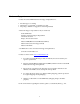
Customer Support Contact the Comtech EF Data Customer Support Department for: • Product support or training • Information on upgrading or returning a product • Reporting comments or suggestions concerning manuals A Customer Support representative may be reached at: Comtech EF Data Attention: Customer Support Department 2114 West 7th Street Tempe, Arizona 85281 USA 480.333.2200 (Main Comtech EF Data Number) 480.333.4357 (Customer Support Desk) 480.333.
Table of Contents CHAPTER 1. INTRODUCTION.............................................................................................................1–1 1.1 Introduction 1–1 1.1.1 Features.................................................................................................................................... 1–2 1.1.2 Options...................................................................................................................................... 1–3 1.2 Modem Design 1–3 1.
SLM-5650 Satellite Modem Preface 1.8.3 1.8.4 1.8.5 1.9 Data Quality Performance ...................................................................................................... 1–11 1.8.3.1 OM-73 Compatible Mode Performance .................................................................. 1–11 1.8.3.2 MIL-STD-188-165A Compatible Mode Performance .............................................. 1–11 1.8.3.3 IESS-308 Compatible Mode Performance .........................................................
SLM-5650 Satellite Modem Preface CHAPTER 3. 3.1 Revision 2 CONFIGURATION..........................................................................................................3–1 Modes 3–1 3.2 Clocking Options 3–11 3.2.1 IDR/IBS G.703 Master/Master ................................................................................................ 3–11 3.2.2 IDR/IBS G.703 Master/Slave .................................................................................................. 3–11 3.
SLM-5650 Satellite Modem Preface CHAPTER 5. Revision 2 MAINTENANCE..............................................................................................................5–1 5.1 System Checkout 5–1 5.1.1 Checkout................................................................................................................................... 5–2 5.1.2 Interface Checkout.................................................................................................................... 5–2 5.1.
SLM-5650 Satellite Modem Preface Revision 2 Figures Figure 1-1. SLM-5650 .............................................................................................................................. 1–1 Figure 1-2. SLM-5650 Block Diagram...................................................................................................... 1–4 Figure 1-3. Dimensional Envelope......................................................................................................... 1–18 Figure 2-1.
SLM-5650 Satellite Modem Preface Revision 2 Tables Table 1-1. Summary of Specification ....................................................................................................... 1–8 Table 1-2. Acquisition and Timing Performance Requirements ............................................................ 1–10 Table 1-3. Doppler Requirements.......................................................................................................... 1–11 Table 1-4. Viterbi Decoder BER.................
SLM-5650 Satellite Modem Preface Revision 2 About this Manual This manual describes the installation and operation for the Comtech EF Data SLM-5650 Satellite Modem. This is a technical document intended for earth station engineers, technicians, and operators responsible for the operation and maintenance of the SLM-5650.
SLM-5650 Satellite Modem Preface Revision 2 Conventions and References Cautions and Warnings CAUTION CAUTION indicates a hazardous situation that, if not avoided, may result in minor or moderate injury. CAUTION may also be used to indicate other unsafe practices or risks of property damage. WARNING indicates a potentially hazardous situation that, if not avoided, could result in death or serious injury. WARNING IMPORTANT indicates a statement that is associated with the task being performed.
SLM-5650 Satellite Modem Preface Revision 2 Metric Conversion Metric conversion information is located on the inside back cover of this manual. This information is provided to assist the operator in cross-referencing English to Metric conversions. Recommended Standard Designations Recommended Standard (RS) Designations are equivalent to the designation of the Electronic Industries Association (EIA). Comtech EF Data will reference only one designator throughout the manual.
SLM-5650 Satellite Modem Preface Revision 2 European EMC Directive In order to meet the European Electro-Magnetic Compatibility (EMC) Directive (EN55022, EN50082-1), properly shielded cables for DATA I/O are required. More specifically, these cables must be shielded from end-to-end, ensuring a continuous ground shield. The following information is applicable for the European Low Voltage Directive (EN60950): ! Type of power cord required for use in the European Community.
SLM-5650 Satellite Modem Preface Revision 2 Warranty Policy This Comtech EF Data product is warranted against defects in material and workmanship for a period of one year from the date of shipment. During the warranty period, Comtech EF Data will, at its option, repair or replace products that prove to be defective. For equipment under warranty, the customer is responsible for freight to Comtech EF Data and all related custom, taxes, tariffs, insurance, etc.
SLM-5650 Satellite Modem Preface Revision 2 Notes: ______________________________________________________________________________ ______________________________________________________________________________ ______________________________________________________________________________ ______________________________________________________________________________ ______________________________________________________________________________ ________________________________________________________________
Chapter 1. Introduction This chapter describes an overview of the SLM-5650 Satellite Modem, referred to in this manual as “the modem” (Figure 1-1). Figure 1-1. SLM-5650 1.1 Introduction The SLM-5650 satisfies the requirements for applications that require state-of-the-art modulation and coding techniques to optimize satellite transponder bandwidth usage while retaining backward compatibility in government and military communications systems.
SLM-5650 Satellite Modem Introduction Revision 2 MN/SLM5650.IOM 1.1.
SLM-5650 Satellite Modem Introduction Revision 2 MN/SLM5650.IOM 1.1.2 Options How Enabled FAST FAST FAST FAST Hardware Hardware 1.
SLM-5650 Satellite Modem Introduction 64 kbps to 20 Mbps Revision 2 MN/SLM5650.
SLM-5650 Satellite Modem Introduction 1.4 Revision 2 MN/SLM5650.IOM Operating Modes The modem supports Closed Network, Open Network and OM-73 modes of operation described as follows. 1.4.1 Closed Networks Closed networks refer to private networks with modem operational parameters that do not need to interoperate with modems developed for commercial open networks, as specified under the IESS308, IESS-309, and IESS-310.
SLM-5650 Satellite Modem Introduction Revision 2 MN/SLM5650.IOM 1.5.1 TIA/EIA-530 The TIA/EIA-530 interface supports the physical layer requirements for TIA/EIA-530. It also supports the TIA/EIA-422 electrical interface specification. This interface operates in duplex from 64 kbps to 20 Mbps. 1.5.2 TIA/EIA-613 (HSSI) The TIA/EIA-613 interface supports the physical layer requirements for TIA/EIA-613. It also supports the TIA/EIA-612 electrical interface specification.
SLM-5650 Satellite Modem Introduction 1.7 Revision 2 MN/SLM5650.IOM Interoperability 1.7.1 Interoperability with Legacy Modems The modem is fully compatible and interoperable with all specified modes of operation of the following legacy modems: a. OM-73 (V) b. MD-1352 (P)/U (BEM-7650) c. MD-1340 (OM-73 interoperable mode only; orderwire not required) d. MD-1030B e. SLM-3650 f. SLM-8650 g. SLM-7650 Note: The remote control protocol will not be backwards compatible. 1.7.
SLM-5650 Satellite Modem Introduction 1.8 Revision 2 MN/SLM5650.IOM Summary of Specifications Table 1-1.
SLM-5650 Satellite Modem Introduction Revision 2 MN/SLM5650.IOM Table 1-1.
SLM-5650 Satellite Modem Introduction Revision 2 MN/SLM5650.IOM 1.8.1 Performance 1.8.2 Acquisition and Timing Performance Requirements Note: The following reference Eb/No is defined as the required Eb/No corresponding to a BER of IE-3 with R-S FEC not enabled. Table 1-2.
SLM-5650 Satellite Modem Introduction Revision 2 MN/SLM5650.IOM Table 1-3. Doppler Requirements Parameter Doppler Shift in Hz C-Band ± 2475 X-Band ± 3535 Ku-Band ± 6045 Ka-Band ± 11,810 Doppler Rate of Change in Hz/sec Doppler Acceleration in Hz/sec2 ± 226 ± 243 ± 270 ± 290 ± 490 ± 526 ± 1046 ± 1124 1.8.3 Data Quality Performance 1.8.3.1 OM-73 Compatible Mode Performance Operating in the OM-73-compatible mode, SLM-5650 BER vs.
SLM-5650 Satellite Modem Introduction 1.8.3.3 Revision 2 MN/SLM5650.IOM IESS-308 Compatible Mode Performance When operating in the IESS-308 Compatible Mode, SLM-5650 BER vs. Eb/N0 performance is as specified in IESS-308. 1.8.3.4 IESS-309 Compatible Mode Performance When operating in the IESS-309 Compatible Mode, SLM-5650 BER vs. Eb/N0 performance is as specified in IESS-309. 1.8.3.5 IESS-310 Compatible Mode Performance When operating in the IESS-310 Compatible Mode, SLM-5650 BER vs.
SLM-5650 Satellite Modem Introduction Revision 2 MN/SLM5650.IOM 1.8.3.8 BER 1.8.3.8.1 BPSK/QPSK/Offset QPSK BER Performance, Viterbi Decoding Table 1-4 applies to BPSK, QPSK, and OQPSK rates. Table 1-4. Viterbi Decoder BER BER 10-3 10-4 10-5 10-6 10-7 10-8 1.8.3.8.2 Eb/No (dB) Specification Viterbi Decoder 1/2 Rate 3/4 Rate 7/8 Rate 3.8 5.0 6.3 4.7 5.9 7.1 5.3 6.6 7.8 5.9 7.2 8.4 6.5 7.8 9.0 7.1 8.3 9.5 Uncoded 10.8 11.6 12.4 13.
SLM-5650 Satellite Modem Introduction 1.8.3.8.3 Revision 2 MN/SLM5650.IOM 8-PSK BER Performance, Trellis Decoder Table 1-6 applies to 8-PSK with trellis decoder rates. Table 1-6. 8-PSK BER Performance, Trellis Decoder Eb/No (dB) Specifications Viterbi Decoder BER 2/3 Rate 5/6 Rate 10-3 6.5 8.7 10-4 7.3 9.4 10-5 8.1 10.1 10-6 8.9 10.8 10-7 9.6 11.6 10-8 10.2 12.3 1.8.3.8.4 8-PSK BER Performance, Trellis Decoder and Reed-Solomon Table 1-7 applies to 8-PSK with trellis decoder and reed-solomon rates.
SLM-5650 Satellite Modem Introduction 1.8.3.8.6 Revision 2 MN/SLM5650.IOM BER Performance, Turbo Products Code Decoding Table 1-9 applies to Turbo Products Code (TPC) decoding rates. Table 1-9. BER Performance, TPC Decoding BER 10-6 10-7 10-8 10-9 10-10 Eb/No (dB) Specification BPSK QPSK/OQPSK 21/44 5/16 21/44 3/4 7/8 3.3 2.5 3.3 3.9 4.3 3.4 2.8 3.4 4.1 4.4 3.5 3.1 3.5 4.3 4.5 3.6 3.4 3.6 4.8 4.6 3.7 3.7 4.7 BER 10-6 10-7 10-8 10-9 10-10 Eb/No Specification 8-PSK 16-QAM 3/4 7/8 17/18 3/4 7/8 6.5 7.
SLM-5650 Satellite Modem Introduction Revision 2 MN/SLM5650.IOM 1.8.4 BER Performance with Symmetrical Adjacent Carriers Operating in the presence of two adjacent symmetrical carriers (one lower in frequency and one higher in frequency with same modulation, data rate, and coding), the modem performance is not degraded more than as indicated in Table 1-10, Column three, and a and b.
SLM-5650 Satellite Modem Introduction Revision 2 MN/SLM5650.IOM 1.8.5 BER Performance with Asymmetrical Adjacent Carriers Operating in the presence of two adjacent asymmetrical carriers, one lower in frequency and one higher in frequency, and each adjacent carrier symbol rate (R"s) = 2.0 R's, the modem performance is not degraded more than indicated in Table 1-10, Column four, and a and b.
SLM-5650 Satellite Modem Introduction 1.9 Revision 2 MN/SLM5650.IOM Dimensional Envelope Figure 1-3.
Chapter 2. INSTALLATION This chapter provides unpacking and installation instructions, system options, and a description of external connections and backward alarm information. CAUTION 2.1 The equipment contains parts and assemblies sensitive to damage by Electrostatic Discharge (ESD). Use ESD precautionary procedures when touching, removing, or inserting PCBs. Unpacking The modem and manual are packaged in pre-formed, reusable, cardboard cartons containing foam spacing for maximum shipping protection.
SLM-5650 Satellite Modem Installation Revision 2 MN/SLM5650.IOM 2.2 Installation 2.2.1 Optional Installation of Side-Railings Install optional side-railings (FP/SL0006), as follows: Quantity 2 Part Number FP/SL0006 Description Side-Railings Use standard shop tooling. Install the side-railings with customer-furnished standard shop hardware. Figure 2-1.
SLM-5650 Satellite Modem Installation 2.2.2 Revision 2 MN/SLM5650.IOM Optional Installation Using a Typical Customer Rack Step 1 2 3 4 5 6 7 Procedures Mount the modem chassis in the assigned position of the equipment rack. Support the modem by either a rack-mounted shelf, or the two rear rackmounted brackets supplied with the unit. Note: For a custom rack installation, refer to the rack drawing in Figure 2-1. Additional information can be obtained from Comtech EF Data Customer Support: www.
SLM-5650 Satellite Modem Installation 2.3 Revision 2 MN/SLM5650.IOM External Connections The connectors on the rear panel of the SLM-5650 are shown in Figure 2-4 and described in the following paragraphs.
SLM-5650 Satellite Modem Installation Revision 2 MN/SLM5650.IOM 2.3.1 External Reference, (J1) The external reference uses a standard 50 Ω, TNC female connector. TNC Connector EXT REF Reference J1 Description External Reference 1, 5, 10 MHZ Direction Input 2.3.2 70 / 140 IF Interface Connectors The 70 / 140 IF use standard 50 Ω, TNC female connectors. TNC Connector Rx Tx Reference J3 J11 Description 52-88, 104-176 MHz Receive 52-88, 104-176 MHz Transmit Direction Input Output 2.3.
SLM-5650 Satellite Modem Installation Revision 2 MN/SLM5650.IOM 2.3.5 EIA-530 Connector, (J6) The Data connector is a 25-pin ‘D’ type female (DB25-F). This connector conforms to the EIA530 pin-out for EIA-422 operation only.
SLM-5650 Satellite Modem Installation Revision 2 MN/SLM5650.IOM 2.3.6 HSSI Connector, (J7) Notes: 1. 52-pin connector 2. These are non-HSSI defined signals. On Cisco routers there is no connection to those pins.
SLM-5650 Satellite Modem Installation Revision 2 MN/SLM5650.IOM 2.3.7 Alarms Connector, (J8) The alarm connector provides Form C contact closures for alarm reporting. The three Form C summary fault contacts are Modulator, Demodulator Common Equipment. The alarm connection is a 9-pin female D connector (J8) located on the rear panel of the modem. Screw locks are provided for mechanical security on the mating connector.
SLM-5650 Satellite Modem Installation Revision 2 MN/SLM5650.IOM (15-Pin Connector) The auxiliary connection is a 15-pin female D connector (J9) located on the rear panel of the modem. Screw locks are provided for mechanical security on the mating connector. Pin # 1 2 3 4 5 6 7 8 9 10 11 12 13 14 15 Signal Function Chassis Ground Spare Demod Q channel AGC Monitor test point Tx TTL fault Spare Ext carrier off Demod I channel Rx TTL fault Name GND Q AGC TxFLT EXT I RxFLT 2.3.
SLM-5650 Satellite Modem Installation Revision 2 MN/SLM5650.IOM 2.3.10 Overhead Data, (P1) The overhead interface connector is a 25-pin male D interface located on the rear panel of the modem. This connector pin-out allows for connection of EIA-422, EIA-485 and EIA-232 data interfaces for use with overhead framing.
SLM-5650 Satellite Modem Installation 2.4 Revision 2 MN/SLM5650.IOM AC Power Connector A standard, detachable, non-locking, 3-prong power cord (IEC plug) supplies the Alternating Current (AC) power to the modem. Observe the following: Input Power Input Voltage Connector Type Fuse Protection 2.5 65W maximum, 50W typical 90 to 132 or 175 to 264 VAC Unit switches ranges automatically I.E.
SLM-5650 Satellite Modem Installation Revision 2 MN/SLM5650.IOM This page is intentionally left blank.
Chapter 3. Configuration 3.1 Modes The following tables show the various data rate ranges available for various modes. Table 3-1. OM-73 Mode Data Rate (kbps) Modulation Type BPSK 1/1 BPSK 1/2 BPSK 3/4 BPSK 7/8 QPSK 1/1 QPSK 1/2 QPSK 3/4 QPSK 7/8 OQPSK 1/1 OQPSK 1/2 OQPSK 3/4 OQPSK 7/8 Min 64 64 64 64 64 64 64 64 64 64 64 64 Max 8472 15000 22500 26250 20000 30000 45000 51840 20000 30000 45000 51840 3–1 Symbol Rate (ksps) Min 64 128 85.333 73.142 32 64 42.666 36.571 32 64 42.666 36.
SLM-5650 Satellite Modem Configuration Revision 2 MN/SLM5650.IOM Table 3-2.
SLM-5650 Satellite Modem Configuration Revision 2 MN/SLM5650.IOM Modulation Type R-S Code Word R-S Depth OQPSK 7/8 OQPSK 7/8 OQPSK 7/8 OQPSK 7/8 8-PSK 2/3 8-PSK 2/3 8-PSK 2/3 8-PSK 2/3 8-PSK 5/6 8-PSK 5/6 8-PSK 5/6 8-PSK 5/6 126,112 219,201 225,205 220,200 126,112 219,201 225,205 220,200 126,112 219,201 225,205 220,200 4, 8 4, 8 4, 8 4, 8 4, 8 4, 8 4, 8 4, 8 4, 8 4, 8 4, 8 4, 8 Data Rate (kbps) Min Max 64 46666.666 64 48184.931 64 47833.333 64 47727.
SLM-5650 Satellite Modem Configuration Modulation Type QPSK 3/4 QPSK 3/4 QPSK 3/4 QPSK 3/4 QPSK 3/4 QPSK 3/4 QPSK 3/4 QPSK 3/4 QPSK 3/4 QPSK 3/4 QPSK 3/4 QPSK 3/4 QPSK 3/4 QPSK 3/4 QPSK 3/4 QPSK 3/4 QPSK 3/4 QPSK 3/4 QPSK 3/4 QPSK 3/4 QPSK 3/4 QPSK 3/4 QPSK 3/4 QPSK 3/4 QPSK 3/4 QPSK 3/4 QPSK 3/4 QPSK 3/4 QPSK 3/4 QPSK 7/8 QPSK 7/8 QPSK 7/8 QPSK 7/8 QPSK 7/8 QPSK 7/8 QPSK 7/8 QPSK 7/8 QPSK 7/8 QPSK 7/8 QPSK 7/8 QPSK 7/8 QPSK 7/8 QPSK 7/8 QPSK 7/8 QPSK 7/8 QPSK 7/8 QPSK 7/8 QPSK 7/8 QPSK 7/8 QPSK 7/8 QPSK 7
SLM-5650 Satellite Modem Configuration Modulation Type QPSK 7/8 QPSK 7/8 QPSK 7/8 QPSK 7/8 QPSK 7/8 QPSK 7/8 QPSK 7/8 QPSK 7/8 QPSK 7/8 QPSK 7/8 QPSK 7/8 QPSK 7/8 QPSK 7/8 QPSK 7/8 QPSK 7/8 QPSK 7/8 QPSK 7/8 QPSK 7/8 QPSK 7/8 Revision 2 MN/SLM5650.
SLM-5650 Satellite Modem Configuration Revision 2 MN/SLM5650.IOM Table 3-4.
SLM-5650 Satellite Modem Configuration Revision 2 MN/SLM5650.
SLM-5650 Satellite Modem Configuration Revision 2 MN/SLM5650.IOM Table 3-5.
SLM-5650 Satellite Modem Configuration Revision 2 MN/SLM5650.IOM Table 3-6.
SLM-5650 Satellite Modem Configuration Revision 2 MN/SLM5650.IOM Table 3-8. 16-QAM Mode Modulation Type R-S Code Word R-S Depth 16-QAM 3/4 16-QAM 3/4 16-QAM 3/4 16-QAM 7/8 16-QAM 7/8 16-QAM 7/8 None 219,201 208,192 None 219,201 208,192 None 4, 8, 16 4, 8, 16 None 4, 8, 16 4, 8, 16 Data Rate ( kbps) 256 256 256 256 256 256 51840 51840 51840 51840 51840 51840 Symbol Rate ( ksps) 85.333 92.975 92.889 73.143 79.692 79.
SLM-5650 Satellite Modem Configuration 3.2 Revision 2 MN/SLM5650.IOM Clocking Options Clocking of the data from the terrestrial equipment to the satellite (and vice versa) will depend on the application. This section describes the most common options and recommended configurations. SCT (INTERNAL) clock no longer applies when the modem has loop timing on. The TX clock source is now recovered from the RX satellite data.
SLM-5650 Satellite Modem Configuration Revision 2 MN/SLM5650.
SLM-5650 Satellite Modem Configuration Revision 2 MN/SLM5650.
SLM-5650 Satellite Modem Configuration 3.3 Revision 2 MN/SLM5650.IOM Buffering The purpose of a receive buffer is two reasons: • • Plesiochronous buffering of two dissimilar clock frequencies (normally the far end transmit clock verses the local network clock). The clocks may be very close in frequency to each other and will normally slip at a constant rate. Figure 3-3 shows plesiochronous operation for dissimilar clocks. If incoming traffic is too fast, an occasional bit will be lost.
SLM-5650 Satellite Modem Configuration Revision 2 MN/SLM5650.IOM PLESIOCHRONOUS OPERATION f1 f1 IS NOT EXACTLY EQUAL TO f 2 f2 2) INCOMING TRAFFIC TOO SLOW 1) INCOMING TRAFFIC TOO FAST BIT 1 BIT 1 BIT 1 ERROR BIT 2 BIT 2 BIT 3 BIT 5 BIT 2 BIT 2 BIT 3 BIT 4 BIT 1 BIT 3 BIT 3 BIT 3 BIT 5 BIT 4 BIT 4 BIT 6 BIT 6 BIT 7 BIT 5 BIT 5 BIT 7 BIT 6 INTERFACE BIT 6 INTERFACE Figure 3-3.
SLM-5650 Satellite Modem Configuration Revision 2 MN/SLM5650.IOM SATELLITE MOTION AND ORBITAL INCLINATION N A GEO-SYNCHRONOUS INCLINED ORBIT GEO-SYNCHRONOUS EQUATORIAL ORBIT A SATELLITE IS MAINTAINED AT AN ASSIGNED GEOSTATIONARY LOCATION THROUGH THE USE OF GROUND COMMAND ADJUSTMENTS TO ITS N/S AND E/W LOCATION. THIS SATELLITE PROCESS, KNOWN AS SATELLITE NOMINAL STATION-KEEPING, IS USED TO KEEP POSITION THE SATELLITE DRIFT WITHIN CERTAIN BOUNDARIES.
SLM-5650 Satellite Modem Configuration Revision 2 MN/SLM5650.IOM 3.3.1 Buffer Size The depth of the receive buffer will depend on four parameters: • • • • 3.4 Doppler shift caused by satellite Stability of each clock (plesiochronous/Doppler operation) Frame/Multiframe length of multiplexed data format Allowable time between clock slips Doppler A geostationary satellite should be positioned directly over the equator and orbit with duration of 24 hours.
SLM-5650 Satellite Modem Configuration 3.5 Revision 2 MN/SLM5650.IOM Plesiochronous The stability of station reference clocks is normally 1 x 10-12 (derived from a cesium standard). While the stability is exceptionally high, the two clocks are not in synchronization with each other and will eventually pass by each other. The clock used for the transmit signal is passed over the satellite, but will not be used at the receive earth station where a national network derives its time locally.
SLM-5650 Satellite Modem Configuration 3.6 Revision 2 MN/SLM5650.IOM Frame/Multiframe Length The depth of the receive buffer required is applicable to all unframed data. When the data is framed (such as 2048 kbps G732 or 1544 kbps G733), it is desirable to provide slips in predefined locations. The advantage of organized slip locations (in relation to the frame) is that multiplexing equipment does not lose sync and outages on any channel are kept to a minimum.
SLM-5650 Satellite Modem Configuration Revision 2 MN/SLM5650.
Chapter 4. FRONT PANEL OPERATION This chapter describes the front panel operation of the modem, including the menus and their explanations, and clocking information. For information about remote control operation, refer to Appendix B. 4.1 Front Panel The modem front panel (Figure 4-1) enables the user to control modem configuration parameters and display the modem status. Figure 4-1.
SLM-5650 Satellite Modem Front Panel Operation Revision 2 MN/SLM5650.IOM The front panel features include: • • • • • • 40-character, 2-line LCD display 6-button keypad for local control 12-button array for manual data entry 8 LEDs to provide overall status at a glance On/Off Power switch USB Port All functions are accessible at the front panel by entering one of six predefined Function Select categories or levels: • • • • • Configuration Monitor Test Save/Load Utility 4.1.
SLM-5650 Satellite Modem Front Panel Operation Revision 2 MN/SLM5650.IOM The indicators are defined as follows: LED Unit Status Tx Status Rx Status Tx On Color Condition Green Red Blinking Green Orange Status No Unit Faults or Stored Faults A Unit Fault exists There are Stored Faults.
SLM-5650 Satellite Modem Front Panel Operation Revision 2 MN/SLM5650.IOM 4.1.2 Front Panel Keypad The front panel keypad controls the local operation of the modem. The keypad consists of 18 keys. Each key provides one or more logical functions. [ENTER] [CLEAR] g and h i and j Numbers +/- IMPORTANT This key is used to select a displayed function, or to execute a modem configuration change.
SLM-5650 Satellite Modem Front Panel Operation Revision 2 MN/SLM5650.IOM 4.1.3 Menu Matrix Select: Configuration 4.3.1) Monitor (4.3.2) Transmit (4.3.1.1) Receive (4.3.1.2 Mod AUPC (4.3.1.3) (4.3.1.4) Ref (4.3.1.5) Mask Reset Remote (4.3.1.6) (4.3.1.7) (4.3.1.8) Alarms (4.3.2.1) Event-Log (4.3.2.2) Rx-Params (4.3.2.3) Statistics (4.3.2.4) Gigabit IF Statistics (4.3.2.
SLM-5650 Satellite Modem Front Panel Operation 4.2 Revision 2 MN/SLM5650.IOM Opening Screen This screen is displayed when power switch is in the On position: Comtech SLM-5650 Modem Firmware Version x.x.x Status: Mode: GO TURBO The bottom line displays the internal software version and the selected mode of operation. Press [ENT] to go to the Main Menu screen. IMPORTANT 4.
SLM-5650 Satellite Modem Front Panel Operation Revision 2 MN/SLM5650.IOM 4.3.1 Select: Config CONFIG: Transmit Receive Mode AUPC Ref Mask Reset Remote (efE) The following choices are presented: Transmit Permits the user to configure the Tx parameters. Receive Permits the user to configure the Rx parameters. Mode Permits the user to configure the modem operating modes. AUPC Permits the user to configure the AUPC parameters. This menu only appears if the modem type has been set to AUPC.
SLM-5650 Satellite Modem Front Panel Operation 4.3.1.1 Revision 2 MN/SLM5650.IOM Select: CONFIG: Transmit Tx: Mod DataRate Overhead Frequency Power Clocking Misc (efE) Mod DataRate Overhead Frequency Power Clocking Misc Permits the user to select: FEC, Type, Rate, RS, Diff, and Scrambler. Permits the user to enter a selected data rate and view the symbol rate. (See Chapter 3.) Permits the user to select the overhead type, view the overhead rate, select the Reed Solomon Code Word, and depth.
SLM-5650 Satellite Modem Front Panel Operation Revision 2 MN/SLM5650.IOM IMPORTANT When changing Modulation type the data rate must be set to a rate supported by the modulation type or the change to the modulation type will not be allowed. Some choices will only be visible if the modem is set to a compatible mode or if an option is installed or enabled. Select: CONFIG: Transmit: DataRate Tx Data Rate: Sym Rate: 020000.000 kbps 0266666.
SLM-5650 Satellite Modem Front Panel Operation Revision 2 MN/SLM5650.IOM Select: CONFIG: Transmit: Frequency Tx Frequency: Spectrum: 1955.0000 MHz Normal (efbcE) Edit the Tx Frequency, using either step 1 or 2: 1. Key in the desired frequency using the numbered keypad. 2. Select the digit to be edited, using the arrow keys. The value of the digit is then changed using the arrow keys.
SLM-5650 Satellite Modem Front Panel Operation Revision 2 MN/SLM5650.IOM Select: CONFIG: Transmit: Clocking Tx Clocking: CLK Source: SCT (efE) SCT Ref: Reference Select Clk Source or SCT Ref, then press [E]. Clk Source SCT Ref SCT or Tx-Terr SCT stands for Send Clock Timing or also is referred to as internal and is provided as an output to provide a clock reference for the user. Tx-Terr stands for the transmit clock input on the selected data interface.
SLM-5650 Satellite Modem Front Panel Operation Revision 2 MN/SLM5650.IOM Note: Framing is applicable only when using externally framed data, with the following formats: T1 or E1 G.704 T2 G.743, G.704, G.707 E2 G.742, G.704, G.745 Select: CONFIG: Receive: Demod Demod: FEC:VIT RS:N/A Diff:On Type:BPSK Rate:3/4 Descram:OM-73 (efE) Select the Demod, Type, RS, Diff, and Descram. Use the ef arrow keys to scroll through all the choices. The user should then press [E].
SLM-5650 Satellite Modem Front Panel Operation Revision 2 MN/SLM5650.IOM Select: CONFIG: Receive: DataRate Rx Data Rate: Sym Rate: 020000.000 kbps 0266666.666 ksps (efbcE) The user can enter the desired data rate using step 1 or step 2 as follows: 1. Use the number keypad and enter the desired data rate (see Chapter 3). 2. Use the efbc arrow keys to scroll up and down to select the desired data rate or symbol rate.
SLM-5650 Satellite Modem Front Panel Operation Revision 2 MN/SLM5650.IOM Select: CONFIG: Receive: Frequency Rx Frequency: Spectrum: 1955.0000 MHz Normal (efE) Edit the Rx Frequency, using either step 1 or 2: 1. Key in the desired frequency using the numbered keypad. 2. Select the digit to be edited, using the arrow keys. The value of the digit is then changed using the arrow keys.
SLM-5650 Satellite Modem Front Panel Operation Revision 2 MN/SLM5650.IOM Select: CONFIG: Receive: Buffer Buffer: Src:RX-Sat Center: Y/N Size:00001024 Mode:Bits Framing (efE) Rx-Sat, Int, or Tx-Terr. Rx-Sat is the recovered clock from the received carrier. Int is a clock synthesized from the modems reference (internal or external). Tx-Terr is the transmit clock supplied by the user. Yes or No, the buffer is automatically centered when the demodulator locks.
SLM-5650 Satellite Modem Front Panel Operation Revision 2 MN/SLM5650.IOM Mode: Modem:TURBO FreqBand:L-Band Interface:EIA-530 Select Modem Type, FreqBand or Interface, then press (efE) [E]. Modem: OM-73 MIL-165A IESS-308 IESS-309 IESS-310 TURBO 16-QAM AUPC Frequency Band Interface IMPORTANT This selects Linkabit OM-73 modem compatibility mode. This selects functionality defined by MIL-STD-188-165A. This selects functionality defined by IESS-308, the Intelsat Intermediate Data Rate standard.
SLM-5650 Satellite Modem Front Panel Operation 4.3.1.4 Revision 2 MN/SLM5650.IOM Select: Configuration: AUPC: Local Local AUPC: Enable: Off Power Settings Target Setting Carrier Loss Action (efE) Select either Enable, Power Settings, Target Settings, or Power Loss Action, then press (E). Enable Power Settings Target Settings Carrier Loss Action On or Off: Allows the user to enable AUPC on the local modem.
SLM-5650 Satellite Modem Front Panel Operation 4.3.1.5 Revision 2 MN/SLM5650.IOM Select: CONFIG: Ref Reference: Internal Ext-1Mhz Ext-5Mhz Ext-10Mhz (efE) Select Internal, Ext-1Mhz, Ext-5Mhz or Ext-1Mhz, then press [E]. Internal Ext-1MHz Ext-5MHz Ext-10MHz 4.3.1.
SLM-5650 Satellite Modem Front Panel Operation 4.3.1.7 Revision 2 MN/SLM5650.IOM Select: CONFIG: Reset Are you sure that you want to default the modem configuration? No Yes (efE) IMPORTANT 4.3.1.8 When selecting RESET all parameters in the modem get reset to the default settings. This includes the real time clock and the stored configurations.
SLM-5650 Satellite Modem Front Panel Operation Revision 2 MN/SLM5650.IOM Select: CONFIG: Remote: Remote: Serial: Interface If Interface was selected: M&C Bus Interface: RS232 RS485-4W TTL (Switching) RS485-2W (efE) Select RS232, RS485-2W (2-wire), or RS485-4W (4-wire), or TTL (Switching) using the arrow keys, then press [E]. The TTL (Switch) selection enables interoperation with the CRS-311 (1:1) or CRS-300 (1:N) switch.
SLM-5650 Satellite Modem Front Panel Operation Revision 2 MN/SLM5650.IOM Select: CONFIG: Remote: Remote: Ethernet If Ethernet was selected: Ethernet Config: IP Address/Range Gateway SNMP GigaBit I/F Addr IP Address/Range MAC Gateway SNMP GigaBit Interface Address/Range MAC Permits the user to select the IP address . Displays the modem’s MAC address, this is programmed at the factory and is not user changeable. If installed, the Gigabit Ethernet interface’s MAC address will also be displayed.
SLM-5650 Satellite Modem Front Panel Operation 4.3.2.1 Revision 2 MN/SLM5650.
SLM-5650 Satellite Modem Front Panel Operation Revision 2 MN/SLM5650.IOM Select: Monitor: Alarms: Transmit: Mod 1st Position If Mod 1st character was selected. Mod: +--Intf: ---- Mod symbol clk not locked. Select: Monitor: Alarms: Transmit: Intf 1st Position If Intf 1st character was selected. Mod: ---Intf: +--- TXIntf data not locked. Select: Monitor: Alarms: Receive: Demod 1st Position If Demod 1st character is selected.
SLM-5650 Satellite Modem Front Panel Operation 4.3.2.2 Revision 2 MN/SLM5650.IOM Select: Monitor: Event-Log Stored Events: View Clear-All (efE) View Clear-All IMPORTANT Permits the user to view the stored faults. The modem will store up to 255 fault events. Permits the user to clear all stored faults. To view the details of a stored fault select an event number by pressing enter. Then scroll through the listed faults for a description of the fault.
SLM-5650 Satellite Modem Front Panel Operation 4.3.2.3 Revision 2 MN/SLM5650.IOM Select: Monitor: Rx-Params Fc=+05917 RSL<-60.0 dBm BERT=N/A Buf=000% Eb/No=Loss BER <1.0E-12 (efE) FC RSL BERT Buf Eb/No BER Permits the user to view the received carrier frequency offset in Hz. The range is the same as the acquisition range of the modem, 60 kHz. Permits the user to view the signal level of the received carrier in dBm. The range supported is +15 to –60 dBm. Permits the user to view the measured BER.
SLM-5650 Satellite Modem Front Panel Operation 4.3.2.5 Revision 2 MN/SLM5650.IOM Select: Monitor: GigaBit I/F Statistics GigaBit Ethernet Card Statistics: View Clear-All Permits the user to view the link statiscal counters. Permits the user to clear or reset the FPGA link error counter. View Clear-All This menu will not appear unless a GigaBit Ethernet Interface is plugged into the modem. IMPORTANT 4.3.
SLM-5650 Satellite Modem Front Panel Operation 4.3.3.1 Revision 2 MN/SLM5650.IOM Select: Test: BERT BERT: Tx:Off Pattern:2047 ErrIns (efE) Reset Rx:Off Errs:=0000000 BER:NoSync Tx Pattern Mark Space 1:1 1:3 2E15-1 2E20-1 2E23-1 MIL188 2047 ErrIns Reset Rx Errs BER IMPORTANT Permits the user to turn the transmit test pattern generator On or Off. Permits the user to select a number of test data patterns. Means, all one’s. Means, all zero’s. Means, a one followed by a zero and then repeats.
SLM-5650 Satellite Modem Front Panel Operation 4.3.3 Revision 2 MN/SLM5650.IOM Select: Save/Load Save/Load: Loc:0 Empty Action: View (efE) Permits the user to select the location to either save or load a configuration. There are 10 locations available, 0 – 9. Permits the user to select either Save or load the selected location. View is the default setting that allows the user to select the location before loading or saving.
SLM-5650 Satellite Modem Front Panel Operation Revision 2 MN/SLM5650.IOM Select: Utility: RT-Clk Edit Real-Time Clock: 15:34:25 27/09/05 (bcefE) Select: Utility: RefAdjust Internal 10 MHz Ref Freq Fine Adjust: 3F3 (bcefE) Select: Utility: AGC AgcMan: Min Value Max Value 4.3.4.1 Min Value: 00.0 Volts Max Value: 10.0 Volts (efE) Permits the user to specify the voltage to output on the External AGC voltage signal when the demodulator RSL is at it’s minimum level.
SLM-5650 Satellite Modem Front Panel Operation Revision 2 MN/SLM5650.IOM Select: Utility: Firmware: Information: Bootrom Bootrom: FW11186-1- 05/13/05 1.1.1 Select: Utility: Firmware: Information: Image#1 Image#1: Bulk App M&C Mod Demod Decoder Filters TxIntfc RxIntfc Turbo (efE) Image# Bulk App M&C Mod Demod Decoder Filters TxIntfc RxIntfc Turbo The following information is displayed: the firmware number including the revision, the release date and the version number.
SLM-5650 Satellite Modem Front Panel Operation 4.3.4.2 Revision 2 MN/SLM5650.IOM Select: Utility: FAST FAST: Configuration View Options S/N 000000012 (efE) Select: Utility: FAST: Configuration FAST Configuration: Enter TURBO Code Modem Code TURBO Code Demo Mode Enter Modem Code Demo Mode (efE) This is a 20 digit code, that allows upgrading the modem functionality, which can be purchased from Comtech EF Data . Legal characters are hexadecimal, 0-F.
SLM-5650 Satellite Modem Front Panel Operation Revision 2 MN/SLM5650.IOM Options 8,9,10 and 11 should be standard with the base modem and do not need to occupy a FAST option slot. IMPORTANT 4.3.4.3 Display Screen Saver Status Modem Status 01 02 03 04 05 06 07 The screen saver has two functions, one is to keep a fixed image from “burning” the screen, and the second is to provide a running status of the modem by scrolling the information sideways.
Chapter 5. MAINTENANCE This chapter contains system checkout, fault isolation, and identification information. 5.1 System Checkout This section provides instructions for checking the modem setup within the earth station. Due to the complexity of the modem circuitry, the checkout procedure should be used only as a basic guideline. Maintenance tests that are more complicated are beyond the scope of this manual.
SLM-5650 Satellite Modem Maintenance Revision 1 MN/SLM5650.IOM 5.1.1 Checkout 5.1.2 Interface Checkout Use the following procedure and the test setup in Figure 5-1 to verify the data interface. NOISE GENERATOR TX IF MODEM UNDER TEST VAR ATTEN RX IF BERT DATA CONNECTORS VAR ATTEN BER TEST SET Figure 5-1. Fault Isolation Test Setup Notes: 1. Ensure the correct data and IF interface is selected and configured for the proper mode of operation. 2.
SLM-5650 Satellite Modem Maintenance Revision 1 MN/SLM5650.IOM 5.1.3 Modulator Checkout Use the following procedure to check out the modulator: Step 1 2 3 4 Procedure Set up the equipment as shown in Figure 5-1 using 70/140 MHz IF interface. Refer to Chapter 1 for the modulator specifications. Set up the modem for IF loopback operation by using the Test\Loopback\IF from the front panel menu, or use an external IF loop.
SLM-5650 Satellite Modem Maintenance Revision 1 MN/SLM5650.IOM Table 5-1. Conversion to S/N and Eb/N0 Chart (dB) (S+N)/N 4.0 4.5 5.0 5.5 6.0 6.5 7.0 7.5 8.0 8.5 9.0 9.5 10.0 10.5 11.0 11.5 12.0 12.5 13.0 13.5 14.0 14.5 15.0 15.5 16.0 16.5 17.0 17.5 18.0 18.5 19.0 19.5 20.0 Code S/N 1.8 2.6 3.3 4.1 4.7 5.4 6.0 6.6 7.3 7.8 8.4 9.0 9.5 10.1 10.6 11.2 11.7 12.2 12.8 13.3 13.8 14.3 14.9 15.4 15.9 16.4 16.9 17.4 17.9 18.4 18.9 19.5 20.0 Rate 1/2 Eb/N0 1.8 2.6 3.3 4.1 4.7 5.4 6.0 6.6 7.3 7.8 8.4 9.0 9.5 10.
SLM-5650 Satellite Modem Maintenance Revision 1 MN/SLM5650.IOM RL -49.00 dBm ATTEN 10 dB 2.00 dB/DIV RES BANDWIDTH 10.0 kHz Modem Rate = 2144 kbit/s, 3/4 Rate Coding with 7.7 dB Eb/No (S + N)/N = 10 dB CENTER 70.000 MHz *RB 10.0 kHz *VB 10.0 Hz SPAN 1.000 MHz ST 30.00 sec Figure 5-2. Typical Output Spectrum (with Noise) RL -20.29 dBm ATTEN 10 dB 5.00 dB/DIV CENTER FREQUENCY 140.000 MHz CENTER 140.000 MHz *RB 30.0 kHz PASS *VB 3.00 Hz SPAN 5.000 MHz ST 166.7 sec Figure 5-3.
SLM-5650 Satellite Modem Maintenance 5.2 Revision 1 MN/SLM5650.IOM Demodulator Checkout Test the demodulator as follows: Step 1 2 3 4 Procedures Set up the equipment as shown in Figure 5-1 using the 70/140 MHz IF interface. Set up the modem with an external IF loop and level. Use a properly operating modulator, and ensure that power levels, data rates, code rates, etc. are compatible. Allow the modem to lock up. a. Depending on the data rate and overhead type, lock-up may take several seconds. b.
SLM-5650 Satellite Modem Maintenance Revision 1 MN/SLM5650.IOM PC version IQ monitor with noise Oscilloscope WITH NOISE Figure 5-4.
SLM-5650 Satellite Modem Maintenance Revision 1 MN/SLM5650.IOM PC version IQ monitor WITHOUT NOISE Oscilloscope WITHOUT NOISE Figure 5-4.
SLM-5650 Satellite Modem Maintenance 5.3 Revision 1 MN/SLM5650.IOM Fault Isolation The design of the modem allows for removal and replacement of some faulty components in the field. The optional interface PCB’s can be removed from the modem through the rear panel, without requiring special tools. The TURBO PCB and power supply can be replaced if the top cover is removed. CAUTION This equipment contains parts and assemblies sensitive to damage by ESD.
SLM-5650 Satellite Modem Maintenance Revision 1 MN/SLM5650.IOM System faults are reported in the “Monitor/Alarms” menu, and stored faults are reported in the “Monitor/Event-Log” menu. To determine the appropriate action for repairing the modem, refer to Table 5-2 and the list of possible problems.
SLM-5650 Satellite Modem Maintenance Revision 1 MN/SLM5650.IOM Table 5-2.
SLM-5650 Satellite Modem Maintenance Revision 1 MN/SLM5650.IOM Table 5-2. SLM-5650 Fault Tree (Continued) T X T X T X R X R X I F S T A T U S F A U L T S T A T U S F A U L T O U T P U T O F F UNIT FAULTS NONE +5.0V POWER +3.3V POWER +2.5V POWER +1.
SLM-5650 Satellite Modem Maintenance 5.4.1 Revision 1 MN/SLM5650.IOM LED Display and Description The 8 LED’s indicate fault, status, and alarm information located on the modem’s front panel. COLOR RED YELLOW GREEN STATUS LED’s A RED COLOR indicates a fault currently exists. It is stored in the Event Log memory. A YELLOW COLOR indicates an alarm currently exists. It is stored in the Event Log memory. A GREEN COLOR indicates no faults or alarms currently exist.
SLM-5650 Satellite Modem Maintenance Revision 1 MN/SLM5650.
Appendix A. OPTIONS A.1 Forward Error Correction Options As standard, the SLM-5650 Modem is equipped with three Forward Error Correction encoders/decoders – Viterbi, concatenated Reed-Solomon, and Trellis (which is available with the 8-PSK FAST option). The constraint lengths and encoding polynomials are not only Open Network compatible, but are also Closed Network compatible with the vast majority of existing modems from other manufacturers.
SLM-5650 Satellite Modem Options A.2 Revision 1 MN/SLM5650.IOM Viterbi The combination of convolutional coding and Viterbi decoding has become an almost universal standard for satellite communications. The SLM-5650 complies with the Intelsat IESS 308 and 309 standards for Viterbi decoding with a constraint length of seven. This is a de facto standard, which means inter-operability with other manufacturer’s equipment.
SLM-5650 Satellite Modem Options A.3 Revision 1 MN/SLM5650.IOM Reed-Solomon Outer Codec The concatenation of an outer Reed-Solomon (R-S) Codec with a Viterbi decoder first became popular in the early 1990's. It permits significant improvements in error performance without significant bandwidth expansion. The coding overhead added by the R-S outer Codec is typically around 10%, which translates to a 0.4 dB power penalty for a given link.
SLM-5650 Satellite Modem Options Revision 1 MN/SLM5650.IOM Closed Network Modes A 225,205 code is used in closed network mode. For a rate of 225,205 data is put into blocks of 225 bytes, of which 205 bytes are data, and 20 bytes are FEC overhead. The code was chosen because it is compatible with legacy Comtech EF Data modems. For closed network Viterbi Reed Solomon, an interleaver depth of 8 is used. The increase in coding gain is at the expense of delay.
SLM-5650 Satellite Modem Options Revision 1 MN/SLM5650.IOM Table A-3. Concatenated RS Coding Summary A.4 FOR AGAINST Exceptionally good BER performance several orders of magnitude improvement in link BER under given link conditions. Very small additional bandwidth expansion Interoperable with legacy Intelsat networks Very pronounced threshold effect - does not fail gracefully in poor Eb/No conditions. Additional coding overhead actually degrades sync threshold, and reduces link fade margin.
SLM-5650 Satellite Modem Options Revision 1 MN/SLM5650.IOM Table A-4. 8-PSK/TCM Coding Summary A.
Appendix B. REMOTE CONTROL B.1 Introduction This section describes the protocol and message command set for remote monitor and control of the SLM-5650 Modem. The electrical interface is either an EIA-485 multi-drop bus (for the control of many devices) or an EIA-232 connection (for the control of a single device), and data is transmitted in asynchronous serial form, using ASCII characters.
SLM-5650 Satellite Modem Remote Control Revision 1 MN/SLM5650.IOM but only one (the intended) will reply. The target enables its output line driver, and transmits its return data packet back to the controller, in the other direction, on the physically separate pair. EIA 485 (full duplex) summary: • • • B.3 Two differential pairs - one pair for controller to target, one pair for target to controller. Controller-to-target pair has one line driver (controller), and all targets have linereceivers.
SLM-5650 Satellite Modem Remote Control B.5 Revision 1 MN/SLM5650.IOM Packet Structure Controller-to-target: Start of Packet Target Address < ASCII code 60 (1 character) (4 characters) Example: Address De-limiter / ASCII code 47 Instruction Code (1 character) (3 characters) Code Qualifier = or ? ASCII code 61 or 63 (1 character) Optional Arguments End of Packet Carriage Return ASCII code 13 (n characters) (1 character) <0135/TFQ=70.
SLM-5650 Satellite Modem Remote Control IMPORTANT B.5.3 Revision 1 MN/SLM5650.IOM The controller sends a packet with the address of a target the destination of the packet. When the target responds, the address used is the same address, to indicate to the controller the source of the packet. The controller does not have its own address. Instruction Code This is a three-character alphabetic sequence, which identifies the subject of the message.
SLM-5650 Satellite Modem Remote Control Revision 1 MN/SLM5650.IOM From Target to Controller, the only permitted values are: Symbol = (ASCII code 61) Definition The ‘=’ code is used in two ways: a. If the controller has sent a query code to a target (Example: TFQ? (meaning ‘what’s the Transmit frequency?’), the target would respond with TFQ=xxxx.xxxx, where xxxx.xxxx represents the frequency in question. b.
SLM-5650 Satellite Modem Remote Control B.6 Revision 1 MN/SLM5650.
SLM-5650 Satellite Modem Remote Control Parameter Type Modem Operating Mode Command (Instruction Code and Qualifier) Arguments for Command or Response to Query MOM= 1 byte, value 0 thru 7 Revision 1 MN/SLM5650.IOM Description of Arguments Command or Query. Modem Operating Mode, where: x=Defines the operating mode, where: 0=OM-73 1=Mil-165A 2=IESS-308 3=IESS-309 4=IESS-310 5=TURBO 6=16QAM 7=AUPC Modem RF Band RFB= 1 byte, value 0 or 1 Example: MOM=0 (sets OM-73 operating mode) Command or Query.
SLM-5650 Satellite Modem Remote Control Parameter Type Tx Frequency Command (Instruction Code and Qualifier) Arguments for Command or Response to Query TFQ= 9 bytes Revision 1 MN/SLM5650.IOM Description of Arguments Command or Query. Tx Frequency, 52 to 88 MHz, 104 to 176 MHz, and 950 MHz to 2000 MHz. Resolution=100Hz. Response to Command Query (Instruction Code and Qualifier) Response to Query TFQ= TFQ? TFQ* TFQ# TFQ? TFQ=xxxx.
SLM-5650 Satellite Modem Remote Control Command (Instruction Code and Qualifier) Arguments for Command or Response to Query Tx FEC Type TFT= 1 byte, value of 0 thru 2 Tx Modulation Type TMD= 1 byte, value of 0 thru 4 Parameter Type Revision 1 MN/SLM5650.IOM Description of Arguments Command or Query. Tx FEC coding type, where: 0=None (Uncoded) 1=Viterbi 2=Turbo Example: TFT=2 (which is Turbo coding) Command or Query.
SLM-5650 Satellite Modem Remote Control Parameter Type Tx Data Rate Tx Reed-Solomon Encoding Command (Instruction Code and Qualifier) Arguments for Command or Response to Query TDR= 10 bytes TRS= 1 byte, value of 0 or 1 Revision 1 MN/SLM5650.IOM Description of Arguments Command or Query. Tx Data rate, in kbps. Response to Command Query (Instruction Code and Qualifier) Response to Query TDR? TDR=xxxxxx.xxx (see description of arguments) Resolution=1 bps.
SLM-5650 Satellite Modem Remote Control Parameter Type Tx Reed-Solomon Interleaver Depth Command (Instruction Code and Qualifier) Arguments for Command or Response to Query TRD= 1 byte, value of 0 to 2 Revision 1 MN/SLM5650.IOM Description of Arguments Command or Query.
SLM-5650 Satellite Modem Remote Control Parameter Type Tx Differential Encoding Command (Instruction Code and Qualifier) Arguments for Command or Response to Query TDE= 1 byte Revision 1 MN/SLM5650.IOM Description of Arguments Command or Query.
SLM-5650 Satellite Modem Remote Control Parameter Type Tx Clock Invert Command (Instruction Code and Qualifier) Arguments for Command or Response to Query TCI= 1 byte, value of 0 or 1 Revision 1 MN/SLM5650.IOM Description of Arguments Command or Query. Invert Transmit Clock, where: x=Invert Transmit Clock, where: 0=Normal 1=Inverted Tx Data Invert TDI= 1 byte, value of 0 or 1 Example: TCI=1 (selects Inverted TX Clock) Command or Query.
SLM-5650 Satellite Modem Remote Control Command (Instruction Code and Qualifier) Arguments for Command or Response to Query Tx Carrier State TXO= 1 byte, value of 0 thru 3 Rx Frequency RFQ= 9 bytes Parameter Type Revision 1 MN/SLM5650.IOM Description of Arguments Command or Query.
SLM-5650 Satellite Modem Remote Control Parameter Type Rx Demod type Command (Instruction Code and Qualifier) Arguments for Command or Response to Query RMD= 1 byte, value of 0 thru 4 Revision 1 MN/SLM5650.IOM Description of Arguments Command or Query.
SLM-5650 Satellite Modem Remote Control Parameter Type Rx ReedSolomon Decoding Command (Instruction Code and Qualifier) Arguments for Command or Response to Query RRS= 1 byte, value of 0 or 1 Revision 1 MN/SLM5650.IOM Description of Arguments Command or Query.
SLM-5650 Satellite Modem Remote Control Command (Instruction Code and Qualifier) Arguments for Command or Response to Query Rx Spectrum Invert RSI= 1 byte, value of 0 or 1 Rx Descrambler RDS= 1 byte, value of 0 thru 6 Parameter Type Revision 1 MN/SLM5650.IOM Description of Arguments Command or Query. Rx Spectrum Invert, where: 0=Normal 1=Rx Spectrum Invert Example: RSI=0 (selects Normal) Command or Query. Rx Scrambler state, where: 0 = Off 1 = OM-73 Scrambler 2 = V.35 Scrambler 3 = Modified V.
SLM-5650 Satellite Modem Remote Control Command (Instruction Code and Qualifier) Arguments for Command or Response to Query Rx Clock Invert RCI= 1 byte, value of 0 or 1 Rx Data Invert RDI= 1 byte, value of 0 or 1 Rx Data Fault RDF= 1 byte, value of 0 thru 2 Parameter Type Revision 1 MN/SLM5650.IOM Description of Arguments Command or Query. Invert Receive Clock, where: x=Invert Receive Clock, where: 0=Normal 1=Inverted Example: RCI=1 (selects Inverted RX Clock) Command or Query.
SLM-5650 Satellite Modem Remote Control Command (Instruction Code and Qualifier) Arguments for Command or Response to Query Rx Reacquisition Time REA= 3 bytes Rx Clock Source RCK= 1 byte, value of 0 thru 2 Rx Buffer Programming Mode RBM= 1 byte, value of 0 or 1 Rx Buffer Size RBS= 8 bytes Modem Reference Clock MRC= 1 byte, value of 0 thru 3 Parameter Type Revision 1 MN/SLM5650.IOM Description of Arguments Command or Query. Rx reacquisition time, in Seconds, ranging from 0 to 999.
SLM-5650 Satellite Modem Remote Control Command (Instruction Code and Qualifier) Arguments for Command or Response to Query IP Address IPA= 18 bytes, numerical Carrier Only Test Modes COM= 1 byte, value of 0 thru 2 Loopback Test Modes LOP= 1 byte, value of 0 thru 3 Tx BERT State BTX= 1 byte, value of 0 or 1 Rx BERT State BRX= 1 byte, value of 0 or 1 Parameter Type Revision 1 MN/SLM5650.
SLM-5650 Satellite Modem Remote Control Command (Instruction Code and Qualifier) Arguments for Command or Response to Query Rx BERT Reset BRS= None Rx BERT Errors N/A 7 bytes Rx BERT BER N/A 6 bytes BERT Pattern PAT= 1 byte, value of 0 thru 8 Insert Tx BERT Error BEI= None Circuit ID String CID= 24 bytes Parameter Type Revision 1 MN/SLM5650.IOM Description of Arguments Command only. Reset Rx BERT Example: BRS= Query only. Read the total number of Bit Errors.
SLM-5650 Satellite Modem Remote Control Parameter Type Configuration Save Command (Instruction Code and Qualifier) Arguments for Command or Response to Query CST= 1 byte Revision 1 MN/SLM5650.IOM Description of Arguments Command only. Command causes the modem to store the current configuration in Configuration Memory location defined by the one-byte argument (0 to 9).
SLM-5650 Satellite Modem Remote Control Command (Instruction Code and Qualifier) Arguments for Command or Response to Query Eb/No Alarm Point EBA= 4 bytes Rx Eb/No N/A 4 bytes Parameter Type Rx Signal Level N/A 5 bytes Rx Frequency Offset N/A 5 bytes Buffer Fill State N/A 2 bytes Rx BER N/A 5 bytes Revision 1 MN/SLM5650.IOM Description of Arguments Command or Query. Eb/No alarm point in dB, with a range between 0.1 and 20 dB. Resolution=0.1 dB Example: EBA=12.3 Query only.
SLM-5650 Satellite Modem Remote Control Command (Instruction Code and Qualifier) Arguments for Command or Response to Query Local/Remote Status LRS= 1 byte, value of 0 or 1 Software Revision N/A 43 bytes Software Image IMG= 1 bytes, value of 1 or 2 Serial Number N/A 9 bytes Temperature N/A 3 bytes Parameter Type Revision 1 MN/SLM5650.IOM Description of Arguments Command or Query. Local/Remote status, where: 0=Local 1=Remote Example: LRS=1 (which is Remote) Query only.
SLM-5650 Satellite Modem Remote Control Parameter Type Equipment ID Command (Instruction Code and Qualifier) Arguments for Command or Response to Query N/A 17 bytes Revision 1 MN/SLM5650.IOM Description of Arguments Query only.
SLM-5650 Satellite Modem Remote Control Parameter Type Live Unit Faults Command (Instruction Code and Qualifier) Arguments for Command or Response to Query N/A 8 bytes Revision 1 MN/SLM5650.IOM Description of Arguments Query only. Live Unit Faults are returned as a 32 bit Hexadecimal value. Bit values are defined as follows: 80000000 = +5.0V Power 40000000 = +3.3V Power 20000000 = +2.5V Power 10000000 = +1.
SLM-5650 Satellite Modem Remote Control Parameter Type Live Tx Faults Command (Instruction Code and Qualifier) Arguments for Command or Response to Query N/A 8 bytes Revision 1 MN/SLM5650.IOM Description of Arguments Query only. Live Tx Faults are returned as a 32 bit Hexadecimal value.
SLM-5650 Satellite Modem Remote Control Command (Instruction Code and Qualifier) Arguments for Command or Response to Query Number of Unread stored Events N/A 3 bytes Initialize Events Pointer IEP= None Retrieve next 5 unread Stored Events N/A 110 bytes Clear All Stored Events CAE= None Parameter Type Revision 1 MN/SLM5650.IOM Description of Arguments Query only. Unit returns the Number of stored Events, which remain Unread, in the form xxx. Note: This means unread over the remote control.
SLM-5650 Satellite Modem Remote Control Command (Instruction Code and Qualifier) Arguments for Command or Response to Query Modem Alarm Mask MSK= 6 bytes Statistics Sample Interval SSI= 1 byte Parameter Type Revision 1 MN/SLM5650.IOM Description of Arguments Command or Query.
SLM-5650 Satellite Modem Remote Control Parameter Type Retrieve next 5 unread Stored Statistics Clear All Stored Statistics Command (Instruction Code and Qualifier) Arguments for Command or Response to Query N/A 105 bytes CAS= None Revision 1 MN/SLM5650.IOM Description of Arguments Query only. Unit returns the oldest 5 Stored Statistics, which have not yet been read over the remote control. Reply format: {CR}Subbody{CR}Sub-body{CR}Sub-body{CR}Sub-body{CR}Sub-body, where Sub-body= AA.ABB.
SLM-5650 Satellite Modem Remote Control Revision 1 MN/SLM5650.IOM G.703 Interface Card Remote Control Commands. The following commands are only valid when the G.703 option card is installed in the SLM-5650 modem. Parameter Type Tx Ternary Code Command (Instruction Code and Qualifier) Arguments for Command or Response to Query TTC= 1 byte, value of 0 thru 3 Description of Arguments Command or Query.
SLM-5650 Satellite Modem Remote Control Parameter Type Receive T2 Framing Command (Instruction Code and Qualifier) Arguments for Command or Response to Query T2F= 1 byte, value of 0, 1, 3, or 5 Revision 1 MN/SLM5650.IOM Description of Arguments Command or Query. Receive T2 Framing, where: 0=None 1=G.704 3=G.743 5=G.747 Receive E2 Framing E2F= 1 byte, value of 0, 1, 2, or 4 Example: T2F=0 Command or Query. Receive E2 Framing, where: 0=None 1=G.704 2=G.742 4=G.
SLM-5650 Satellite Modem Remote Control Revision 1 MN/SLM5650.IOM Automatic Uplink Power Control (AUPC) Remote Control Commands. The following commands are only valid when the SLM-5650 modem type has been set to AUPC. Note: Always wait 3 seconds between consecutive remote modem command/query polls. If Local AUPC is not enabled, query commands will return the last known condition. A request for status from the remote modem will then be transmitted, ensuring that the next query will return current status.
SLM-5650 Satellite Modem Remote Control Command (Instruction Code and Qualifier) Arguments for Command or Response to Query AUPC Minimum Power Level AMN= 5 bytes AUPC Eb/N0 Target Set Point AET= AUPC Maximum Tracking Rate AMT= AUPC Local Carrier Loss Action LCL= AUPC Remote Carrier Loss Action RCL= Parameter Type Revision 1 MN/SLM5650.IOM Description of Arguments Command or Query. Minimum Tx Output power level, where: s=sign ( + / - ) xx.x = Tx Output power level, +10.0 and –40.0 dBm.
SLM-5650 Satellite Modem Remote Control Command (Instruction Code and Qualifier) Arguments for Command or Response to Query Remote Modem AUPC Enable RPC= 1 byte, values of 0 or 1 Remote Modem Pattern Substitution RPB= Parameter Type Revision 1 MN/SLM5650.IOM Description of Arguments Command or Query. Remote Modem AUPC Control, where: 0=Off 1=On 1 byte, values of 0 or 1 Example: RPC=1 (Turn on remote modem AUPC Control) Command or Query.
SLM-5650 Satellite Modem Remote Control Parameter Type Global Configuration Command (Instruction Code and Qualifier) Arguments for Command or Response to Query MGC= 177 bytes, with numerical entries, fixed values and delimiters Revision 1 MN/SLM5650.IOM Response to Command Description of Arguments MGC= MGC? MGC* MGC# Command or Query. Global Configuration of SLM-5650, in the form: abcdeeeeeefghijkkkkkkkklmnoooooo.ooopppp.ppppqrrrstuvwxyyy. yzABCDEFGHHHHHHHHIJKLLLLLL.LLLMMMM.
SLM-5650 Satellite Modem Remote Control Parameter Type Command (Instruction Code and Qualifier) Arguments for Command or Response to Query Revision 1 MN/SLM5650.IOM Response to Command Description of Arguments A = Tx SCT Reference B = Tx Clock Invert C = Tx Data Invert D = Tx Data Fault E = Tx BPSK Data Ordering F = Tx Carrier State G = Tx Ternary Code HHHHHHHH = expansion bytes I = Rx FEC Type J = Rx Modulation Type K = Rx Code Rate LLLLLL.LLL = Rx Data Rate MMMM.
SLM-5650 Satellite Modem Remote Control Parameter Type Command (Instruction Code and Qualifier) Arguments for Command or Response to Query Revision 1 MN/SLM5650.IOM Response to Command Description of Arguments J = Receive T2 Framing K = Receive E2 Framing L = External Buffer Clock Reference M = AUPC Local Enable NNN.N = AUPC Nominal Power Level OOO.O = AUPC Maximum Power Level PPP.P = AUPC Minimum Power Level QQ.Q = AUPC Eb/No Target Level R.
SLM-5650 Satellite Modem Remote Control Revision 1 MN/SLM5650.
SLM-5650 Satellite Modem Remote Control Revision 1 MN/SLM5650.IOM This page is intentionally left blank.
Appendix C. FLASH UPGRADING The SLM-5650 eliminates the need for updating firmware by physically replacing EPROMs. Instead, the SLM-5650 modem uses ‘flash memory’ technology internally, and new firmware can be uploaded to the unit from an external PC, as follows: • • • Go to: www.comtechefdata.com Click on: downloads Click on: flash upgrades This makes software upgrading very simple, and updates can now be sent via the Internet, E-mail, or on disk.
SLM-5650 Satellite Modem Reflash Revision 1 MN/SLM5650.IOM 2. Create a temporary directory (folder) on your PC. Windows: Select File > New > Folder > and rename the New Folder to "temp" or another convenient and unused name. Assuming "temp" works, you should now have a "c:\temp" folder created. Note: The c: is the drive letter used in this example. Any valid writable drive letter can be used.
SLM-5650 Satellite Modem Reflash Revision 1 MN/SLM5650.IOM Verify the communication and connection by issuing a "ping" command to the modem. You can find the IP address of the modem either remotely using the <0/IPA? command or from the front panel with the menus. To PING and FTP from DOS, press the “Start” button on the Windows toolbar, and select the “Run...” option. From Win95 or Win98, type, “command”. From WinNT, Win2K or WinXP, type “cmd”.
SLM-5650 Satellite Modem Reflash Revision 1 MN/SLM5650.IOM 10. Verify the new software versions are booting by observing the following messages on the modem display: Comtech SLM-5650 Modem Firmware Version: 1.1.
Appendix D. ETHERNET MANAGEMENT D.1 Introduction The base modem is equipped with an RJ-45, 10/100BaseT Ethernet management interface used for monitor and control purposes. This chapter of the manual will provide a high-level overview of the functionality provided by this interface and references other chapters for further details. D.
SLM-5650 Satellite Modem Ethernet Management D.3 Revision 1 MN/SLM5650.IOM Web Server (HTTP) Interface The embedded Web Server application provides the user with an easy to use interface to configure and monitor all aspects of the Base Modem. These web pages have been designed for optimal performance when using Microsoft’s Internet Explorer 5.5 or higher. By typing http://xxx.xxx.xxx.xxx” (where xxx.xxx.xxx.xxx =Base Modem IP address) on your browser, the Login prompt will appear.
SLM-5650 Satellite Modem Ethernet Management D.4 Revision 1 MN/SLM5650.IOM Web Server Menu Tree Table D-1.
SLM-5650 Satellite Modem Ethernet Management D.5 Revision 1 MN/SLM5650.IOM SNMP Interface The Simple Network Management Protocol (SNMP) is an application-layer protocol designed to facilitate the exchange of management information between network devices. The SLM-5650 SNMP agent supports both SNMPv1 and v2c. IMPORTANT D.5.1 For proper SNMP operation, the SLM-5650 MIB files must be used with the associated version of the SLM-5650 base modem M&C.
SLM-5650 Satellite Modem Ethernet Management D.5.2 Revision 1 MN/SLM5650.IOM SNMP Community Strings The modem uses community strings as a password scheme that provides authentication before gaining access to the modem agent’s MIBs. In “SNMP v1/v2c”, the community string is sent unencrypted in the SNMP packets. Caution must be taken by the network administrator to ensure that SNMP packets travel only over a secure and private network if security is a concern.
SLM-5650 Satellite Modem Ethernet Management Revision 1 MN/SLM5650.IOM The following tables are the Alarms and Faults v1 traps / v2 notifications that the modem supports. Alarms and Faults SNMPv1 traps: slm5650TxTrafficAlarmV1 6247282 slm5650UnitAlarmV1 6247281 slm5650RedundancyStateV1 6247283 slm5650RedundancyStateV1 6247284 Alarms and Faults SNMPv2 notifications: slm5650UnitAlarmV2 1.3.6.1.4.1.6247.28.2.1.1. slm5650TxTrafficAlarmV2 1.3.6.1.4.1.6247.28.2.1.2 slm5650RxTrafficAlarmV2 1.3.6.1.
SLM-5650 Satellite Modem Ethernet Management Revision 1 MN/SLM5650.
SLM-5650 Satellite Modem Ethernet Management Revision 1 MN/SLM5650.IOM There is a disadvantage when using Windows DOS as Telnet Client. Since Windows DOS cannot translate a ‘\r’ to a ‘\r\n’ for the messages coming from Telnet Server, the multi-line command response (for example, FRW? response) will be displayed as one line, with the latter lines overwriting the previous lines. In order to view the full response messages, CEFD recommends using HyperTerminal configured as Telnet Client.
SLM-5650 Satellite Modem Ethernet Management Revision 1 MN/SLM5650.
SLM-5650 Satellite Modem Ethernet Management Revision 1 MN/SLM5650.
Appendix E. 10/100/1000 Base-T (GbE) Interface E.1 Introduction The 1000 Base-T Ethernet Interface or GbE acts as an Ethernet bridge for data traffic. The GbE Interface is shown in Figure E-1. Monitor and Control (M&C) information is not supported on the GbE Interface but is available through the 10/100 Base-T remote port of the modem. The GbE Interface is 10/100/1000 Base-T and supports data rates from 1 Mbps to 155 Mbps.
SLM-5650 Satellite Modem CDI-70 Gigabit Ethernet Interface E.2 Revision 1 MN/SLM5650.IOM Physical Description The GbE is implemented on a 4.5 W x 6.8 D x .85 H inches (11.43 W x 17.27 D x 2.16H cm) PCB. Connectivity to the SLM-5650 will be implemented with a 96-pin DIN receptacle, and the LAN interface consists of an RJ-45 connector with link status and link activity Light-Emitting Diode (LED) indicators (at minimum). E.3 General Specifications Table E-1.
SLM-5650 Satellite Modem CDI-70 Gigabit Ethernet Interface Revision 1 MN/SLM5650.
SLM-5650 Satellite Modem CDI-70 Gigabit Ethernet Interface Revision 1 MN/SLM5650.IOM Management Management Packet Packet Processor Processor Clk & Data J1 GE GE Layer Layer 22 Switch Switch Ethernet RJ-45 Interface RJ-45 Packet Packet Processor Processor μC Modem Interface Memory Memory Gigabit Ethernet Card Figure E-2. GbE Interface Option Board E.4 Connector Pinout The LAN interface is comprised of one IEEE 802.3ab 1000Base-T copper interface via a single female RJ-45 connector wired: Table E-2.
SLM-5650 Satellite Modem CDI-70 Gigabit Ethernet Interface Revision 1 MN/SLM5650.IOM E.5 Installation 1000 Base-T Ethernet (GbE) Interface Card Removal and WARNING Ensure the unit is in a Power Off mode. Serious injury or damage to the equipment could result. The card plugs in upside down. Figure E-3. 1000 Base-T Ethernet (GbE) Interface Card Removal of the Interface Card: Steps 1 2 3 4 Procedures Turn power to the modem off. Disconnect the RJ-45 cable from the interface card.
SLM-5650 Satellite Modem CDI-70 Gigabit Ethernet Interface Revision 1 MN/SLM5650.IOM This page is intentionally left blank.
Index A D AC Power Connector, 2-11 Acceptable ACI Degradation with Spacing Factor of 1.
SLM-5650 Satellite Modem Index Revision 2 MN/SLM5650 .IOM P I Performance, 1-10 Plesiochronous, 3-18 Protection Switches, 1-7 IDR/IBS G.703 Master/Master, 3-11 IDR/IBS G.703 Master/Master Clocking Diagram, 3-12 IDR/IBS G.703 Master/Slave, 3-11 IDR/IBS G.
SLM-5650 Satellite Modem Index Revision 2 MN/SLM5650 .
METRIC CONVERSIONS Units of Length Unit Centimeter Inch Foot Yard Mile Meter Kilometer Millimeter 1 centimeter — 0.3937 0.03281 0.01094 6.214 x 10⁻⁶ 0.01 — — 1 inch 2.540 — 0.08333 0.2778 1.578 x 10⁻⁵ 0.254 — 25.4 1 foot 30.480 12.0 — 0.3333 1.893 x 10⁻⁴ 0.3048 — — 1 yard 91.44 36.0 3.0 — 5.679 x 10⁻⁴ 0.9144 — — 1 meter 100.0 39.37 3.281 1.094 6.214 x 10⁻⁴ — — — 1 mile 1.609 x 10⁵ 6.336 x 10⁴ 5.280 x 10³ 1.760 x 10³ — 1.609 x 10³ 1.
2114 WEST 7TH STREET TEMPE ARIZONA 85281 USA 480 • 333 • 2200 PHONE 480 • 333 • 2161 FAX