Installation Manual • • • • Installation Startup Maintenance Parts Models MODCON VWH 300 / LP / HL / LPHL MODCON VWH 500 / LP / HL / LPHL MODCON VWH 850 / LP / HL / LPHL n WARNING This manual must only be used by a qualified heating installer/service technician. Read all instructions in this manual before installing. Perform steps in the order given. Failure to comply could result in severe personal injury, death or substantial property damage. NOTICE Heat Transfer Products, Inc.
GAS-FIRED HOT WATER SUPPLY BOILER Boiler Manual WARNING If the information in this manual is not followed exactly, a fire or explosion may result causing property damage, personal injury or loss of life. • • • 1 Do not store or use gasoline or other flammable vapors and liquids in the vicinity of this or any other appliance. WHAT TO DO IF YOU SMELL GAS Do not try to light any appliance. gas supplier's instructions.
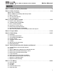
GAS-FIRED HOT WATER SUPPLY BOILER Boiler Manual CONTENTS Part 1 – Product and Safety Information . . . . . . . . . . . . . . . . . . . . . . . . . . . . . . . . . . . . . . . 4 Part 2 – Before You Start . . . . . . . . . . . . . . . . . . . . . . . . . . . . . . . . . . . . . . . . . . . . . . . . . . . 6-8 Mod Con Recovery Ratings Mod Con VWH Recovery Ratings with Storage Tanks A. What’s In The Box B. How The Boiler Operates C. Optional Equipment Part 3 – Prepare Boiler Location . . . . . . . . . . . .
GAS-FIRED HOT WATER SUPPLY BOILER Boiler Manual CONTENTS (CONT’D) Part 8 – Field Wiring. . . . . . . . . . . . . . . . . . . . . . . . . . . . . . . . . . . . . . . . . . . . . . . . . . . . . . 44-51 A. B. C. D. E. F. G. H. I. J. K. L. M. N.
Boiler Manual GAS-FIRED HOT WATER SUPPLY BOILER PART 1: PRODUCT AND SAFETY INFORMATION SPECIAL ATTENTION BOXES The following defined terms are used throughout this manual to bring attention to the presence of hazards of various risk levels or to important information concerning the product. DEFINITIONS n DANGER n CAUTION DANGER indicates an imminently hazardous situation which, if not avoided, will result in death or serious injury.
Boiler Manual GAS-FIRED HOT WATER SUPPLY BOILER PART 1: PRODUCT AND SAFETY INFORMATION (CONT’D) n WARNING CAUTION You must not have a direct connection of the potable water system into the Mod Con VWH heat exchanger which could cause flow issues, short cycling and increase mineral build-up in the unit. The Mod Con VWH System is designed to have the incoming potable water flow through the storage tank first and then flow from the storage tank through the Mod Con heat exchanger.
Boiler Manual GAS-FIRED HOT WATER SUPPLY BOILER PART 2: BEFORE YOU START MODCON RECOVERY RATINGS WATER FLOW AT VARIOUS TEMPERATURE RISE 20Δt 25Δt 30Δt 35Δt 40Δt 45Δt 50Δt 55Δt 60Δt 65Δt 70Δt 75Δt 80Δt 85Δt 90Δt 95Δt 100Δt 105Δt 110Δt 115Δt 120Δt 125Δt 130Δt 135Δt 140Δt Model RECOVERY RATE IN GALLONS PER HOUR BASED ON TEMPERATURE RISE BETWEEN INLET TEMPERATURE AND OUTLET TEMPERATURE ModCon 300 1,692 1,354 1,128 967 564 521 483 451 423 398 376 356 338 322 308 294 282 271 260 251 242 ModC
Boiler Manual GAS-FIRED HOT WATER SUPPLY BOILER PART 2: BEFORE YOU START (CONT’D) Min Tank Size (gal.) = Required flow (GPM) x 10 Mixing factor M f = VWH Outlet Temp– 40 70 First Hour rating = [ Total VWH Output x VWH Efficiency (VWH Outlet Temp-40) x 8.31 +.75 x Total Storage ] x Mf Example: 2 MOD CON VWH 500 Total Output = 1,000,000 BTU @ 94% Efficiency VWH Outlet Temp 140 °F 2 Storage Tanks (80 Gallon Each) Total Storage = 160 Gallons Mixing factor Mf = 140-40 = 1.
GAS-FIRED HOT WATER SUPPLY BOILER Boiler Manual PART 2: BEFORE YOU START (CONT’D) 4. 5. 6. 7. 8. 9. 10. 11. 12. 13. The cascade system is capable of connecting up to eight boilers together in such a way that they function as one boiler system. This allows for greater turn down ratios and provides systematic control of the multiple boilers in an installation to minimize downtime and maximize efficiency.
GAS-FIRED HOT WATER SUPPLY BOILER Boiler Manual PART 3: PREPARE BOILER LOCATION A. BOILER LOCATION / DIMENSIONS Before considering the Boiler location, there are many factors that have to be addressed that are covered in detail in this installation manual. Please read the entire manual as it could save time and money. Piping, Venting, Condensation Removal are just a few issues that need to be addressed prior to the installation of the boiler.
Boiler Manual GAS-FIRED HOT WATER SUPPLY BOILER DIMENSIONS FLOW SWITCH LEFT SIDE (MOD CON 300) POWER SWITCH ACCESS PANEL FRONT (ALL MODELS) RIGHT SIDE (MOD CON 300) DISPLAY PANEL HOT WATER OUTLET ELECTRICAL BOX K A L F N G B GAS LINE C LEGS ADJUST 1-1/4"-3" CONDENSATE DISCHARGE D J E RIGHT SIDE (MOD CON 500/850) REAR (ALL MODELS) EXHAUST AIR INTAKE LEFT SIDE (MOD CON 500/850) ELECTRICAL BOX ACCESS PANEL M VWH MODEL A B C D D F J G H K L M N MOD CON 300* 20.00" 6.
GAS-FIRED HOT WATER SUPPLY BOILER Boiler Manual PART 3: PREPARE BOILER LOCATION (CONTINUED) B. INSTALLATIONS MUST COMPLY WITH: • Local, state, provincial, and national codes, laws, regulations and ordinances. • National Fuel Gas Code, ANSI Z223.1 – latest edition. • Standard for Controls and Safety Devices for Automatically Fired Boilers, ANSI/ASME CSD-1, when required. • National Electrical Code. • For Canada only: B149.1 or B149.2 Installation Code, CSA C22.
Boiler Manual GAS-FIRED HOT WATER SUPPLY BOILER PART 3: PREPARE BOILER LOCATION (CONTINUED) n WARNING E. EXHAUST VENT AND INTAKE AIR VENT n WARNING Vents must be properly supported. The Mod Con’s Intake and Exhaust Connections are not designed to carry heavy weight. Vent support brackets must be within 1 foot of the boiler and the balance at 4 foot intervals. The Mod Con venting must be readily accessible for visual inspection for the first three feet from the boiler.
GAS-FIRED HOT WATER SUPPLY BOILER Boiler Manual PART 3: PREPARE BOILER LOCATION (CONTINUED) connected to the common venting system are located and other spaces of the building. Turn on clothes dryers and any appliance not connected to the common venting system. Turn on any exhaust fans, such as range hoods and bathroom exhausts, so they will operate at maximum speed. Do not operate a summer exhaust fan. Close fireplace dampers. G.
GAS-FIRED HOT WATER SUPPLY BOILER Boiler Manual PART 4: PREPARE BOILER (CONTINUED) enclosure. You can use either a solid ¾” in diameter black iron pipe or lifting straps to lift the boiler off of its shipping crate. You must have at least two individuals to handle the boiler properly to avoid damage as care should be taken as the Mod Con is very heavy. The Mod Con is also equipped with leveling feet that can be used to level the boiler properly if the surface location is not level.
GAS-FIRED HOT WATER SUPPLY BOILER Boiler Manual PART 5: BOILER PIPING (CONTINUED) B. GENERAL PIPING INFORMATION n CAUTION NOTICE The Mod Con Boiler control module uses temperature sensors to provide both high limit protection and modulating temperature control. The control module also provides low water protection by sensing the water flow through the flow switch on the heat exchanger. Some codes/jurisdictions may require additional external controls. C. SYSTEM WATER PIPING METHODS Expansion tank 1.
GAS-FIRED HOT WATER SUPPLY BOILER Boiler Manual PART 5: BOILER PIPING (CONTINUED) n WARNING 2. Thread brass Tee into outlet nipple using pipe dope: Never use dielectric unions or galvanized steel fittings when connecting to a stainless steel storage tank or boiler. n WARNING When raising tank temperature, you increase the risk of scalding – Please use a water tempering or mixing valve and extreme caution. Consult codes for conformance. E.
GAS-FIRED HOT WATER SUPPLY BOILER Boiler Manual PART 5: BOILER PIPING (CONTINUED) 5. Feed Green Ground Wire into Boiler through the wire access: 8. Connect wire harness to the red wire connection on the flow switch: 6. From the front of the boiler, feed the ground wire Up into the control box: 9.
GAS-FIRED HOT WATER SUPPLY BOILER Boiler Manual PART 5: BOILER PIPING (CONTINUED) F. SCALDING This water heater can deliver scalding temperature water at any faucet in the system. Be careful whenever using hot water to avoid scalding injury. Certain appliances such as dishwashers and automatic clothes washers may require increased temperature water.
Boiler Manual GAS-FIRED HOT WATER SUPPLY BOILER PART 5: BOILER PIPING (CONTINUED) Fig. 5-1 below represents the combined flow rates and pipe sizes when using multiple boilers to design the manifold system for the primary circuit. To size, simply add up the number of boilers and the required flow rates for the system design temperature. Flow rate 30 50 60 85 Pipe Dia.
GAS-FIRED HOT WATER SUPPLY BOILER Boiler Manual PART 5: BOILER PIPING (CONTINUED) G. HIGH VELOCITY CIRCULATOR PUMP Every VWH system requires special attention to the pump size in order to overcome the pressure drop through the boiler and its related piping. All circulators installed on the VWH system must be designed for a potable water system. NOTICE Water temperature above 140° requires the circulator pump to run continuously and must have a water hardness of between 5 to 7 grains.
GAS-FIRED HOT WATER SUPPLY BOILER PART 5: BOILER PIPING (CONTINUED) H.
GAS-FIRED HOT WATER SUPPLY BOILER Boiler Manual PART 5: BOILER PIPING (CONTINUED) 22
GAS-FIRED HOT WATER SUPPLY BOILER PART 5: BOILER PIPING (CONTINUED) 23 Boiler Manual
GAS-FIRED HOT WATER SUPPLY BOILER Boiler Manual PART 5: BOILER PIPING (CONTINUED) 24
GAS-FIRED HOT WATER SUPPLY BOILER PART 5: BOILER PIPING (CONTINUED) 25 Boiler Manual
Boiler Manual GAS-FIRED HOT WATER SUPPLY BOILER PART 5: BOILER PIPING (CONTINUED) Drawing VWH 2/2 V MC mechanical aquastat (both tanks) wired in series (preferred) cold water recirculation line ASEE 1017 rated anti-scald valve (recommended) hot water supply Volume Water Heating using MOD CON boilers (2 boilers supplying 2 storage tanks) System/Pipe Sensor Used if sensor cannot be placed at tank – (Important to note that Pumps must be wired to run continuously to operate in this configuration) MOD C
GAS-FIRED HOT WATER SUPPLY BOILER PART 5: BOILER PIPING (CONTINUED) 27 Boiler Manual
GAS-FIRED HOT WATER SUPPLY BOILER Boiler Manual PART 6: VENTING, COMBUSTION AIR & CONDENSATE REMOVAL A. INSTALLING EXHAUST VENT AND INTAKE AIR VENT n DANGER n WARNING Use only the materials listed in Tables 6-1 through 6-7 for the venting systems. Failure to do so could result in severe personal injury, death or substantial property damage. The Mod Con Boiler must be vented as detailed in this section. Ensure the exhaust and intake piping comply with these instructions regarding the venting system.
GAS-FIRED HOT WATER SUPPLY BOILER Boiler Manual PART 6: VENTING, COMBUSTION AIR & CONDENSATE REMOVAL (CONTINUED) Table 6-1 APPROVED PLASTIC EXHAUST VENTING MATERIAL STANDARDS FOR INSTALLATION IN: UNITED STATES CANADA PVC SCHEDULE 40 / 80 ANSI /ASTM D1785 ULC S636** PVC -DWV ANSI /ASTM D2665 ULC-S636** CPVC SCHEDULE 40 / 80 ANSI /ASTM F441 ULC- S636** **Note: IPEX is an approved *Note: Cellular Foam Core Pipe must only Manufacturer in Canada be used on INTAKE piping.
GAS-FIRED HOT WATER SUPPLY BOILER Boiler Manual PART 6: VENTING, COMBUSTION AIR & CONDENSATE REMOVAL (CONTINUED) n WARNING You must not use “B” Vent in an exhaust application. ‘B’ vent is for intake applications only. Failure to do so will result in serious injury or death. intake of a direct-vent appliance. • Provide a minimum of 1 foot distance from any door, operable window, or gravity intake into any building.
GAS-FIRED HOT WATER SUPPLY BOILER Boiler Manual PART 6: VENTING, COMBUSTION AIR & CONDENSATE REMOVAL (CONTINUED) monitors the condensate level to prevent it from backing up into the combustion system. There is a ¾” sweat connection provided to connect the outlet of the collection system to a drain or condensate pump.
Boiler Manual GAS-FIRED HOT WATER SUPPLY BOILER PART 6: VENTING, COMBUSTION AIR & CONDENSATE REMOVAL (CONTINUED) &21'(16$7( 1(875$/,=(5 :,7+287 3803 6:($7 39& 7(( 23(1 72 $70263+(5( 3,3( +$1*(5 $66(0%/,(6 )25 6833257 CONDENSATE OVERFLOW SWITCH NOTE: TO CLEAN OUT CONDENSATE COLLECTOR ;USE A WET VAC INSIDE THE OPEN PORT TO THE CONDENSATE COLLECTOR. THIS WILL HELP REMOVE ANY FOREIGN MATTER THAT MAY BLOCK THE CONDENSATE LINE.
GAS-FIRED HOT WATER SUPPLY BOILER Boiler Manual PART 6: VENTING, COMBUSTION AIR & CONDENSATE REMOVAL (CONTINUED) Location of exit terminals of mechanical draft and direct-vent venting systems. (Reference: National Fuel Gas Code ANSI Z223.1/NFPA 54 2002). Fig. 6-3 Multiple Vents Fig. 6-4 Multiple Vent Spacing* *Note: Exhaust must extend out 1 foot. There should be no more than 2 vents and 2 intakes then a space of 36” to the next set of vents.
Boiler Manual GAS-FIRED HOT WATER SUPPLY BOILER PART 6: VENTING, COMBUSTION AIR & CONDENSATE REMOVAL (CONTINUED) E. EXHAUST VENT AND INTAKE AIR VENT SIZING 1. The exhaust vent and intake air vent pipes are 4" for the Mod Con 300 and 500, and 6" for the Mod Con 850. 2. The total combined equivalent length of exhaust vent and intake air pipe should not exceed 200 feet. a. The equivalent length of elbows, tees, and other fittings are listed in the Friction Loss Table 6-8. a.
GAS-FIRED HOT WATER SUPPLY BOILER Boiler Manual PART 6: VENTING, COMBUSTION AIR & CONDENSATE REMOVAL (CONTINUED) vent pipe. If the exhaust pipe must be piped around an obstacle that results in the creation of a low point, condensate will collect in this low point and form a blockage. This condensate must be drained away using a field-installed condensate drain assembly.
Boiler Manual GAS-FIRED HOT WATER SUPPLY BOILER PART 6: VENTING, COMBUSTION AIR & CONDENSATE REMOVAL (CONTINUED) I. DIAGRAMS FOR SIDEWALL VENTING TWO PIPE SIDEWALL VENTING W/TEE (INTAKE) AND COUPLING (EXHAUST) TWO PIPE SIDEWALL VENTING WITH V-SERIES KIT ,1/(7 (;+$867 6&5((1 VENT KIT (SEE CHART) $,5 ,17$.( 9(17 7(( 0$; 723 9,(: SUPPORT BRACKETS MUST BE USED ON ALL HORIZONTAL AND VERTICAL PIPING 675$,*+7 &283/,1* (;+$867 9(17 EXHAUST VENT 7' OR 1' ABOVE MAX.
Boiler Manual GAS-FIRED HOT WATER SUPPLY BOILER PART 6: VENTING, COMBUSTION AIR & CONDENSATE REMOVAL (CONTINUED) J. DIAGRAM FOR VERTICAL VENTING TWO PIPE ROOF VENTING WITH TEE (INTAKE) AND COUPLING (EXHAUST) ,16(57 ,1/(7 (;+$867 6&5((1 3529,'(' ,172 675$,*+7 &283/,1* ,16(57 ,1/(7 (;+$867 6&5((16 3529,'(' ,172 ($&+ (1' 2) 7(( 675$,*+7 &283/,1* 0,1 7(( 0,1 29(5 0$;,080 612: /(9(/ 25 :+,&+(9(5 ,6 *5($7(5 (;+$867 9(17 5,*+7 6,'( 9,(: Fig.
Boiler Manual GAS-FIRED HOT WATER SUPPLY BOILER PART 6: VENTING, COMBUSTION AIR & CONDENSATE REMOVAL (CONTINUED) 10’ 0" MIN. 24" MIN. ROOF EXHAUST RAIN CAP - STAINLESS STEEL 4" Z-FLEX 2SVSRCF04 6" Z-FLEX 2SVSRC06 DIAGRAM FOR HORIZONTAL VENTING RIZONTAL VENTING AIR INTAKE GALVANIZED/B-VENT 12" OVER MAXIMUM SNOW LEVEL OR 24" WHICHEVER IS GREATER E ROOF VENTING WITH STAINLESS STEEL (AL294C) A A.
Boiler Manual GAS-FIRED HOT WATER SUPPLY BOILER PART 7: GAS PIPING n WARNING Failure to follow all precautions in this section could result in fire, explosion or death! A. GAS CONNECTION The gas supply shall have a maximum inlet pressure of less than 14" w.c. (3.5 kPa), and a minimum of 3.5" w.c. (.87 kPa). The entire piping system, gas meter and regulator must be sized properly to prevent pressure drop greater than 0.5" (.12 kPa) as stated in the National Fuel Gas Code.
Boiler Manual GAS-FIRED HOT WATER SUPPLY BOILER PART 7: GAS PIPING (CONTINUED) C. GAS TABLE Refer to Table 7-1 to size the supply piping to minimize pressure drop between meter or regulator and unit. Maximum Capacity of Pipe in Cubic Feet of Gas per Hour for Gas Pressures of 0.5 w.c. or Less and a Pressure Drop of 0.3 Inch w.c. Table 7-1 NATURAL GAS SUPPLY PIPING CAPACITY CHART (0.6 specific gravity gas; 0.
GAS-FIRED HOT WATER SUPPLY BOILER Boiler Manual PART 7: GAS PIPING (CONTINUED) tor is used, it must be a minimum of 10 feet from the Mod Con. It is very important that the gas line is properly purged by the gas supplier or utility. Failure to properly purge the lines or improper line sizing, will result in ignition failure. This problem is especially noticeable in NEW LP installations and also in empty tank situations.
GAS-FIRED HOT WATER SUPPLY BOILER Boiler Manual PART 7: GAS PIPING (CONTINUED) MOD CON 500 GAS VALVE THROTTLE ADJUSTER NOTE: IF FOR ANY REASON THE THROTTLE NEEDS TO BE ADJUSTED, IT IS VERY IMPORTANT THAT A "COMBUSTION ANALYZER" BE USED TO ENSURE SAFE AND PROPER OPERATION. TURN THE ADJUSTER TO THE (+) TO INCREASE THE GAS OR (-) TO DECREASE THE GAS SUPPLY. THIS ADJUSTMENT COULD AFFECT CO/CO% LEVELS. MAKE SURE THE LEVELS CORRESPOND TO THE CHART IN COMBUSTION SETTINGS. (FIG.
Boiler Manual GAS-FIRED HOT WATER SUPPLY BOILER PART 7: GAS PIPING (CONTINUED) MOD CON 850 GAS VALVE THROTTLE ADJUSTER NOTE: IF FOR ANY REASON THE THROTTLE NEEDS TO BE ADJUSTED, IT IS VERY IMPORTANT THAT A COMBUSTION ANALYZER BE USED TO ENSURE SAFE AND PROPER OPERATION. TURN THE ADJUSTER TO THE (+) TO INCREASE GAS SUPPLY OR TO THE (-) TO DECREASE GAS SUPPLY. THIS ADJUSTMENT COULD AFFECT CO/CO% LEVELS. MAKE SURE THE LEVELS CORRESPOND TO THE CHART IN THE COMBUSTION SETTINGS SECTION (FIG.
GAS-FIRED HOT WATER SUPPLY BOILER Boiler Manual PART 8: FIELD WIRING n WARNING ELECTRICAL SHOCK HAZARD — For your safety, turn off electrical power supply at service entrance panel before making any electrical connections to avoid possible electric shock hazard. Failure to do so can cause severe personal injury or death. NOTICE Wiring must be N.E.C. Class 1. If original wiring as supplied with boiler must be replaced, use only TEW 105 °C wire or equivalent.
GAS-FIRED HOT WATER SUPPLY BOILER Boiler Manual PART 8: FIELD WIRING (CONTINUED) the tank(s) from the boilers as close to the tank(s) as possible. The purpose of this sensor is to serve as feedback to the control to provide it with the aggregate temperature of all boilers firing. The master boiler control will then fire the boilers in cascade sequence to maintain the water in this pipe at the appropriate temperature to provide correct heating of the tank.
GAS-FIRED HOT WATER SUPPLY BOILER Boiler Manual PART 8: FIELD WIRING (CONTINUED) MOD CON VWH CONTROL Fig. 8-1 LP-248-VWH Rev.
GAS-FIRED HOT WATER SUPPLY BOILER Boiler Manual PART 8: FIELD WIRING (CONTINUED) G TANK SENSOR OR MECHANICAL CONTROL Connect the tank sensor or mechanical controls to the TANK SENSOR terminals of the low voltage terminal strip as shown in Fig. 8-1. The control will automatically determine which type of sensor is connected and will operate accordingly. Caution should be used to ensure that neither of these terminals becomes connected to ground. H.
GAS-FIRED HOT WATER SUPPLY BOILER Boiler Manual PART 8: FIELD WIRING (CONTINUED) L. WIRING OF CASCADE SYSTEM COMMUNICATION BUS 1. Use standard CAT3 or CAT5 computer network patch cables to connect the communication bus between each of the boilers. Use standard ‘straight through’ cables for these connections. Do not use crossover cables. These cables are readily available at any office supply, computer, electronic, department or discount home supply store in varying lengths.
GAS-FIRED HOT WATER SUPPLY BOILER Boiler Manual PART 8: FIELD WIRING (CONTINUED) MOD CON VWH Cascade Master NOTE: You must place the Cascade Master label (included in shipping envelope) on top of the Standard Mod Con Control Fig. 8-3 M. MODCON VWH CASCADE MASTER PUMP AND SENSOR WIRING 1. Place the Cascade Master Overlay Sticker onto the field connection board on the boiler designated as the Cascade Master 2.
GAS-FIRED HOT WATER SUPPLY BOILER Boiler Manual PART 8: FIELD WIRING (CONTINUED) MOD CON VWH Cascade Follower Fig. 8-4 N. MODCON VWH CASCADE FOLLOWER PUMP AND SENSOR WIRING 1. If it is desired to have the boiler control the boiler pump, Connect the boiler pump to the BOILER HOT, BOILER NEUT, BOILER GND terminals 2. Connect the tank sensor(s) or return sensor to the terminals marked TANK SENSOR on the follower boiler addressed as 1. There are no connections to these terminals on other LP-248-VWH Rev.
GAS-FIRED HOT WATER SUPPLY BOILER Boiler Manual PART 8: FIELD WIRING (CONTINUED) Fig. 8-5 51 LP-255 Rev.
GAS-FIRED HOT WATER SUPPLY BOILER Boiler Manual PART 9. START-UP OPERATION A. SINGLE MOD CON VWH BOILER When power is applied to the MODCON VWH boiler, the control first completes a power-up systems check. During this time, the combustion fan may run. The display will initially show the current boiler outlet temperature. If a fault is detected during the power-up test time, the control will display the appropriate fault code.
GAS-FIRED HOT WATER SUPPLY BOILER Boiler Manual PART 9. START-UP PREPARATION (CONTINUED) built into the boiler. If this should happen, the master boiler will display an E03 fault code indicating that the supply sensor has failed. C. CHECK FOR GAS LEAKS n WARNING outlet on the Mod Con is lower than the drain, you must use a condensate removal pump, available from Heat Transfer Products (#554200).
GAS-FIRED HOT WATER SUPPLY BOILER Boiler Manual PART 9. START-UP PREPARATION (CONTINUED) 5. Change parameter 23 from 0 to 1. This makes it the master boiler. 6. Exit the installer menu NOTE: The temperature set point of the master must match the follower boiler set point in order for the system to operate properly. 3.
GAS-FIRED HOT WATER SUPPLY BOILER Boiler Manual PART 10. START-UP PROCEDURE FOR YOUR OWN SAFETY READ BEFORE OPERATING 1. This appliance does not have pilot. It is equipped with an ignition device which automatically lights the burner. Do not try to light the burner by hand. 2. BEFORE OPERATING smell all around the appliance area for gas. Be sure to smell next to the floor because some gas is heavier than air and will settle on the floor. WHAT TO DO IF YOU SMELL GAS • • Do not try to light any appliance.
Boiler Manual GAS-FIRED HOT WATER SUPPLY BOILER PART 10.
Boiler Manual GAS-FIRED HOT WATER SUPPLY BOILER PART 10. START-UP PROCEDURE (CONTINUED) Function Value d12/ Power on in hours (display will not read until 100 hrs.) Example : Display number x 1000 = Power on Hours d13/ NA d14/ Total running hours of boiler(s) (display will not read until 100 hrs) d15/ Passed ignition attempts in thousands (display will not read until 100 ignition attempts) Example: Display number x 1000 = Ignition attempts Display showing12.
Boiler Manual GAS-FIRED HOT WATER SUPPLY BOILER PART 11: START-UP PROCEDURES FOR THE INSTALLER (CONTINUED) to normal operation. If the code is entered correctly, the control will switch off the gas valve and purge fan while showing a solid |---| in the display. The display will then show a |1| alternating to |dd|. This first function verifies that the control is configured as a VWH boiler. C. PROGRAM NAVIGATION Next you will have to press the {S/3} key to move through each function.
GAS-FIRED HOT WATER SUPPLY BOILER Boiler Manual PART 11: START-UP PROCEDURES FOR THE INSTALLER (CONTINUED) Function Default Function Number Value Description 23 0 Cascade configuration default 0. Change this to 1 if the boiler is in a cascade system. Range 0-1 24 24 Power on hours for cascade priority change over. This parameter is used to set how many power on hours will go by before the priority boiler will be rotated in the cascade system.
Boiler Manual GAS-FIRED HOT WATER SUPPLY BOILER PART 12: TROUBLESHOOTING A. MOD CON ERROR CODE If any of the sensors detect an abnormal condition or an internal component fails during the operation of the Mod Con Boiler, the display may show an error code.
Boiler Manual GAS-FIRED HOT WATER SUPPLY BOILER PART 12: TROUBLESHOOTING (CONTINUED) n DANGER n CAUTION When servicing or replacing components that are in direct contact with the boiler water, be certain that: • There is no pressure in the boiler. (Pull the release on the relief valve. Do not depend on the pressure gauge reading). • The boiler water is not hot • The electrical power is off This appliance has wire function labels on all internal wiring.
GAS-FIRED HOT WATER SUPPLY BOILER Boiler Manual PART 12: TROUBLESHOOTING (CONTINUED) Table 12-2: 926 Control Board FAULT Codes Code Description F00 F01 F02 F03 F05 F06 F09 F10 F11 F13 F20 PP F31 Remedy 1. Check circulation pump operation 2. Assure that there is adequate flow through the boiler by accessing the status menu and assuring that there is High Temperature Limit less than a 50°F rise from the return thermistor to the supply thermistor. Exceeded. 3.
Boiler Manual GAS-FIRED HOT WATER SUPPLY BOILER PART 12: TROUBLESHOOTING (CONTINUED) Resistance Table System/Pipe Sensor Temperature Sensor 7250P-324 Boiler Sensor (7250P-667) Indirect/Tank Sensor (7250P-325) Water Temperature (°F) Resistance (ohms) 32 41 50 59 68 77 86 95 104 113 122 131 140 149 158 167 176 185 194 203 212 32550 25340 19870 15700 12490 10000 8059 6535 5330 4372 3605 2989 2490 2084 1753 1481 1256 1070 915 786 667 NOTE: If receiving an F09 fault code, check the gap spacing between poi
GAS-FIRED HOT WATER SUPPLY BOILER Boiler Manual PART 13: MAINTENANCE (CONTINUED) n WARNING The combustion chamber insulation in this product contains ceramic fiber material. Ceramic fibers can be converted to cristobalite in very high temperature applications. The International Agency for Research on Cancer (IARC) has concluded, “Crystalline silica inhaled in the form of quartz or cristobalite from occupational sources is carcinogenic to humans (Group1).
GAS-FIRED HOT WATER SUPPLY BOILER Boiler Manual PART 13: MAINTENANCE (CONTINUED) d. Replace and tighten the (6) 10MM nuts to the burner plate using staggered tightening sequence. (See detail) C. MAINTENANCE PROCEDURE TO CLEAN HEAT EXCHANGER: 1. Shut off power to the boiler. 2. Close ball valves on both inlet and outlet of the heater. 3. Attach a hose to both the drain valves located on the inlet and outlet. Feed both hoses into a plastic bucket.
GAS-FIRED HOT WATER SUPPLY BOILER Boiler Manual PART 13: MAINTENANCE (CONTINUED) MOD CON 300 VWH Fig. 13-1 LP-205-A REV.
GAS-FIRED HOT WATER SUPPLY BOILER Boiler Manual PART 13: MAINTENANCE (CONTINUED) MOD CON 500 VWH Fig. 13-2 67 LP-205-V REV.
Boiler Manual GAS-FIRED HOT WATER SUPPLY BOILER PART 13: MAINTENANCE (CONTINUED) MOD CON 850 VWH 02' &21 ,WHP 5HSODFHPHQW 'HVFULSWLRQ 1R 3DUW 3 %78 02' &21 02'8/( 3 %851(5 '225 3 %851(5 '225 5()5$&725< 3 %851(5 3 *$6.
GAS-FIRED HOT WATER SUPPLY BOILER Boiler Manual PART 13: MAINTENANCE (CONTINUED) 13 14 12 9 18 4 11 7 3 10 5 6 15 16 8 1 2 17 ITEM MOD CON 300VWH* MOD CON 500VWH* MOD CON 850VWH* 1 2 3 4 5 6 7 8 9 7500P-033 7500P-100 7250P-059 7250P-667 7350P-089 7500P-002 7350P-003 7350P-071 7350P-014 7500P-033 7500P-100 7250P-059 7350P-667 7350P-089 7500P-002 7350P-004 7350P-072 7350P-015 7500P-033 7500P-100 7250P-059 7350P-667 7350P-089 7500P-002 7350P-004 7350P-072 7350P-015 10 7350P-001 7350P-002
Boiler Manual GAS-FIRED HOT WATER SUPPLY BOILER PART 13: MAINTENANCE (CONTINUED) Item MOD CON 300 VWH* MOD CON 500 VWH* MOD CON 850 VWH* No 1 7350P-039 7350P-040 7350P-041 2 7350P-092 7250P-092 7350P-092 3 7250P-673 7250P-673 7250P-673 4 7350P-067 7250P-068 7250P-069 5 7350P-063 7350P-063 7350P-063 6 7350P-059 7350P-060 7350P-061 7 7350P-053 7350P-055 7350P-057 8 7350P-054 7350P-056 7350P-058 9 7350P-049 7350P-049 73
71 Notes: System Setting 5) Check Combustion Check Mixing Valve ____dh ____*8 ____de ____*9 ____ppm CO Check and adjust (if necessary) carbon monoxide content Verifty system settings High Fire ____% CO2 High Fire High Fire Dynamic Static ____*10 ____ppm CO ____%CO2 ____ μA _______________ Check and adjust (if necessary) carbon dioxide content Turn up aquastat on storage tank to verify wiring connections 4) Verify System Operation ____ μA ____in w.c.
Check condition of all vent pipe and joints and supports. Note any deterioration and replace. Check gas piping, test for gas leaks and signs of aging, make sure all pipes are supported properly.
73 1. Check entire condensate system making sure there are no obstructions in the flow 2. Make sure the condensate pump is working property, verify all connections. 3. Clean out condensate neutralizer, use Wet / Dry Vacuum. Check for all potential obstruction issues. Replenish marble chips or lime crystals if needed (no smaller than ¾”) Refill system with water WARNING: You must verify flow of condensate and make sure the cap is connected properly before leaving boiler unattended.
LP-172 REV.
LP-172 REV.
MAINTENANCE NOTES 76
MAINTENANCE NOTES 77
MAINTENANCE NOTES 78
© 2003–2009 Heat Transfer Products, Inc. www.HTproducts.com LP-276 REV.