C610/C711 User’s Guide 59320301 my.okidata.
Copyright Information Copyright © 2009 by Oki Data. All Rights Reserved C610/C711 User’s Guide P/N 59320301, Revision 1.0 September, 2009 Disclaimer Every effort has been made to ensure that the information in this document is complete, accurate, and up-to-date. The manufacturer assumes no responsibility for the results of errors beyond its control.
Emergency First Aid Take care with toner powder: If swallowed, give small amounts of cold water and seek medical attention. DO NOT attempt to induce vomiting. If inhaled, move the person to an open area for fresh air. Seek medical attention. If it gets into the eyes, flush with large amounts of water for at least 15 minutes keeping eyelids open. Seek medical attention. Spillages should be treated with cold water and soap to help reduce risk of staining skin or clothing.
Contents Introduction . . . . . . . . . . . . . . . . Printer Overview . . . . . . . . . . . C610 Front View . . . . . . . . . C610 Rear View. . . . . . . . . . C711 Front View . . . . . . . . . C711 Rear View. . . . . . . . . . Changing the Display Language Getting Started. . . . . . . . . . . . Power saving mode . . . . . Switching off . . . . . . . . . .............. ............. ............. ............. ............. ............. ............. ............. ............. ............. . . . . . .
Contents (cont.) Available Options . . . . . . . . . . . . . . . . . . . . . . . . . . Duplex (two-sided printing) Unit . . . . . . . . . . . . . Additional RAM Memory . . . . . . . . . . . . . . . . . . . SD Card . . . . . . . . . . . . . . . . . . . . . . . . . . . . . . Additional Paper Tray(s) . . . . . . . . . . . . . . . . . . . . . . . . . . . .67 . . . . . . . . . 67 . . . . . . . . . 67 . . . . . . . . . 68 . . . . . . . . . 68 Troubleshooting . . . . . . . . . . . . . . . . . . . . . . . . . . .
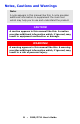
Notes, Cautions and Warnings Note: A note appears in this manual like this. A note provides additional information to supplement the main text which may help you to use and understand the product. CAUTION! A caution appears in this manual like this. A caution provides additional information which, if ignored, may result in equipment malfunction or damage. WARNING! A warning appears in this manual like this.
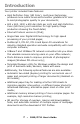
Introduction Your printer includes these features: • High Definition Color (HD Color), multi-level technology produces more subtle tones and smoother gradations of color to lend photographic quality to your documents; • 600 x 600, 1200 x 600 dpi (dots per inch) and High Definition Color (HD Color) print resolution for high quality image production showing the finest detail; • Internet Protocol version 6 (IPv6); • Single Pass color Digital LED technology for high speed processing of your printed pages; • Pos
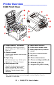
Printer Overview ________________ C610 Front View 9 13 1 10 2 11 7 4 6 13 8 7 12 3 5 1. Output stacker, face down Standard printed copy delivery point. Holds up to 250 sheets at 80 g/m². 2. Operator panel Menu driven operator controls and LCD* panel. 3. Paper tray 5. Paper level indicator 6. Front cover release lever 7. Multi-purpose tray release recess 8. Top cover release button 9. LED heads 10. Fuser release levers Standard paper tray. Holds up to 300 sheets of 80 g/m² paper. 4.
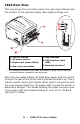
C610 Rear View This view shows the connection panel, the rear output stacker and the location of the optional duplex (two-sided printing) unit. UPDATE IMAGE 4 5 6 7 3 1 2 1. ON/OFF switch 2. AC power socket 5. USB interface 3. Duplex unit (when fitted) 6. ACC interface (host USB) 4. Rear, face up stacker 7. Network interface* * The Network Interface may have a protective “plug” which must be removed before connection can be made.
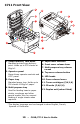
C711 Front View 9 13 1 10 2 11 7 4 6 13 8 7 12 3 5 1. Output stacker, face down Standard printed copy delivery point. Holds up to 350 sheets at 80g/m². 2. Operator panel Menu driven operator controls and LCD* panel. 3. Paper tray 5. Paper level indicator 6. Front cover release lever 7. Multi-purpose tray release recess 8. Top cover release button 9. LED heads 10. Fuser release levers Standard paper tray. Holds up to 530 sheets of 80g/m² paper. 4.
C711 Rear View This view shows the connection panel, the rear output stacker and the location of the optional duplex (two-sided printing) unit. 4 5 7 6 8 3 1 2 1. ON/OFF switch 2. AC power socket 5. USB interface 3. Duplex unit (when fitted) 6. ACC interface (host USB) 4. Rear, face up stacker 7. Network interface* 8. Parallel interface * The Network Interface may have a protective “plug” which must be removed before connection can be made.
Changing the Display Language ____ The default language used by your printer for display messages and for report printing is English. If required, this can be changed to: • French • Spanish • Portuguese Getting Started _________________ Power saving mode If you do not use the machine for a while, it will enter the power saving mode to control the power consumption of the device. To cancel or initiate power saving mode, press the Power Save/ Wake Up button on the control panel.
Paper Recommendations Your printer will handle a variety of print media, including a range of paper weights and sizes, transparencies and envelopes. This section provides general advice on choice of media, and explains how to use each type. The best performance will be obtained when using standard 20 lb. US Bond (75 g/m²) paper designed for use in copiers and laser printers. Use of heavily embossed or very rough textured paper is not recommended.
Tray 1 and Optional Trays 2 and 3___ Media sizes SIZE DIMENSIONS Letter 8.5 x 11 inches Legal 13 8.5 x 13 inches Legal 13.5 8.5 x 13.5 inches Legal 14 8.5 x 14 inches Executive 7.25 x 10.5 inches A5 148 x 210 mm B5 182 x 257 mm A4 210 x 297 mm A61 105 x 148 mm 1. C711: A6 printing from the MP Tray only Media Weight Settings PAPER TYPE WEIGHT (US BOND) WEIGHT (g/m²) Light 16-17 lb. US Bond 60 - 63 g/m2 Medium Light 18 lb. US Bond 64 - 74 g/m2 Medium 20-24 lb.
runs out of paper. When printing from Windows applications, this function is enabled in the driver settings. When printing from other systems, this function is enabled in the Print Menu. (See “Menu Functions” on page 23.) Multi Purpose Tray ______________ The multi purpose tray can handle the same sizes as trays 1, 2 and 3 but in weights up to 67 lb. US Bond (250 g/m²). For very heavy paper stock use the face up (rear) paper stacker. This ensures that the paper path through the printer is almost straight.
Duplex Unit ____________________ This option provides automatic two-sided printing on the same range of paper sizes as tray 2 (i.e. all cassette sizes except A6), using paper stocks from: • C610: 17-32 lb. US Bond (64-120 g/m²) • C711: 17-59 lb. US Bond (64-220 g/m²) Note: The duplex unit comes as standard with dn models.
Loading Paper Note: For illustrative purposes, the C711 printer has been shown. If you have a C610 printer, the principle is the same with any exceptions noted. Tray 1 and Optional Trays 2 and 3___ 1. Remove the paper tray from the printer. 2. Fan the paper to be loaded at the edges (1) and in the middle (2) to ensure that all sheets are properly separated, then tap the edges of the stack on a flat surface to make it flush again (3).
3. Load paper (letter headed paper face down and top edge towards the front of the printer), as shown.
4. Adjust the rear stopper (a) and paper guides (b) to the size of paper being used. CAUTION! C711 ONLY: IMPORTANT: Set paper size dial (c) to the size of paper being used (A4 in the above example). To prevent paper jams: • Do not leave space between the paper and the guides and rear stopper. • Do not overfill the paper tray. Capacity depends on the type of paper stock. • Do not load damaged paper. • Do not load paper of different sizes or types at the same time. • Close the paper tray gently.
capacity is approximately 100 sheets of 20-lb. US Bond (75 g/m2) paper. a b CAUTION! Do not open or close the rear paper exit while printing as it may result in a paper jam.
Multi-Purpose Tray________________________ a c d b d 1. Open the multi purpose tray (a). 2. Fold out the paper supports (b). 3. Press gently down on the paper platform (c) to ensure it is latched down. 4. Load the paper and adjust the paper guides (d) to the size of paper being used. • For single-sided printing on letterhead paper load the paper into the multi purpose tray with pre-printed side up and top edge into the printer.
5. 6. • For two-sided (duplex) printing on letterhead paper load the paper with pre-printed side down and top edge away from the printer. (Optional duplex unit must be installed for this function.) • Envelopes should be loaded face up with top edge to the left and short edge into the printer. Do not select duplex printing on envelopes. • Do not exceed the paper capacity of about 100 sheets or 10 envelopes. Maximum stacking depth is 3/8-inch (10 mm).
Menu Functions This section lists the menus accessed via the controls on the printer’s operator panel and displayed in the LCD window.
Operator Panel: _______________ 2 1 3 4 10 5 1. Ready LED 9 ON: Ready to receive data. 6 2. Display 7 8 Displays the printer status and any error messages. BLINKING: Processing data. OFF: Offline. 3. Menu Scroll Buttons Enters the Menu 4. On Line Button mode. In Menu mode, forwards or reverses the menu item displayed. Press for 2 secs. or longer to jump from top to bottom. Switches between ONLINE and OFFLINE. Exits the menu and goes ONLINE when pressed in the Menu mode. Scrolls the HELP screen.
2 1 4 3 10 5 5. Attention LED 9 ON: A warning occurs. Printing may be possible (e.g low toner). 6 6. Back Button 7 8 Returns to the previous higher level menu item. BLINKING: An error occurs. Printing not possible (e.g. toner empty). OFF: Normal condition. 7. Enter Button In the ONLINE 8. Cancel Button or OFFLINE mode: enters the Menu mode. Deletes the data being printed or received when pressed for two seconds or longer. In the Menu mode: determines the setting selected.
How to Change the Settings: User___ It should be noted that many of these settings can be, and often are, overridden by settings in the Windows printer drivers. However, several of the driver settings can be left at “Printer Setting”, which will then default to the settings entered in these printer menus. Where applicable, factory default settings are shown in bold type in the following tables. In the normal operating condition, known as “standby,” the printer’s LCD window will show “Ready to Print”.
How to Change the Settings: Administrator __________________ You can set whether to ENABLE or DISABLE each category in the user menu. Disabled categories are not displayed in the User’s menu. Only a system administrator can change these settings. 1. Turn OFF the printer. Turn ON the printer while pressing the Enter button. When Boot Menu appears, take your finger off the button. 2. Press the Enter button. 3.
Menus ________________________ Configuration Menu ITEM Tray Count ACTION Tray1 Tray 2* Tray 3* EXPLANATION Select an item to display the total number of pages printed from the relevant tray. MP Tray *Note: Only available when optional trays are present Supplies Life Cyan Drum Magenta Drum Select item to display the percentage of a consumable remaining. Yellow Drum Black Drum Belt Fuser Cyan Toner Magenta Toner Yellow Toner Black Toner Network Printer Name Displays the full printer name.
ITEM System ACTION Serial Number EXPLANATION Displays information for these items. Asset Number Lot Number CU Version PU Version Total Memory Flash Memory SD Card Date and Time a. Display condition: IP Version is IP v4+v6 or IP v6. Print Information Menu This menu provides a quick method of listing various items stored within the printer. ITEM ACTION EXPLANATION Configuration Execute Select execute to print out a configuration report.
ITEM ACTION EXPLANATION EPSON FX Font Execute List Scroll down to this parameter and select execute to print out an Epson FX emulation font list. Usage Report Execute Scroll down to this parameter and select execute to print out a list of color and mono pages printed. Error Log Execute Scroll down to this parameter and select execute to print out the error log. Color Profile List Execute Scroll down to this parameter and select execute to print out a list of color profiles.
Print Secure Job Menu Note: This menu only displays if the optional SD card is installed or on a C610hdn with a hard disk drive installed. ITEM Encrypted Job ACTION Not Found Print Delete EXPLANATION Used for printing an encrypted authentication print job (Encrypted Job) stored in the SD card. After inputting a password, "Searching Job" is displayed until a job appropriate for the password is found.
ITEM Stored Job ACTION EXPLANATION Not Found Used to print out a stored job in the SD card. Print Not Found will be displayed where a file, which could be printed is not available. Delete The following message will appear if a printable file is available. Stored Job Print Delete When Print is selected, Set Collating Amount is displayed and the number of pages to print can be specified. Specify the number of pages to print and press the Enter button.
Menus Menu ITEM Tray Configuration ACTION EXPLANATION Paper feed Default: Tray 1 Select tray. Select by scroll and Enter button. Auto Tray Switch Default: On Switches Auto ON/OFF. Select by scroll and Enter button. Tray Sequence Default: Down Selects Tray sequence Down/Up/ Paper feed Tray. Select by scroll and Enter button. Unit of Measurement Default: inches Selects UOM inches or millimeter. Select by scroll and Enter button. Tray1 Config Default: Configure Paper Size/Media Type/Media Weight.
ITEM Tray Configuration (cont.) ACTION MP Tray Config Paper Size: • A4/A5/A6/B5 • Legal14/Legal 13.5/ Legal13 • Letter • Executive • Custom • Com-9 Envelope • Com-10 Envelope • Monarch Envelope • DL Envelope • C5 • Index Card Media Type: • Plain • Letterhead • Film • Labels • Bond • Recycled • Card Stock • Rough • Glossy • USERTYPE 1-5 EXPLANATION Configure Paper Size/Media Type/Media Weight/Tray Usage. Select by scroll and Enter button. USERTYPE 1 to 5 are displayed only if registered in the host PC.
ITEM ACTION Tray 2 Config Tray 3 Config System Adjust Power Save Time Default: 30 Sleep Time Default: 10 EXPLANATION Note: only present if option installed Select from 1/2/3/4/5/10/15/ 30/60/120/180 Minutes. Select by scroll and Enter button. Select from 1/2/3/4/5/10/15/ 30/60/120/180 Minutes. Select by scroll and Enter button. Clearable Warning Default: ONLINE Auto Continue Default: Off Manual Timeout Default: 60 Select from: ONLINE/Job. Select by scroll and Enter button. PS job only.
ITEM System Adjust (cont.) ACTION Paper Black Setting –2/–1/0/+1/+2 EXPLANATION Used for fine adjustment of the black print on paper. Default: 0 Paper color Setting –2/–1/0/+1/+2 Used for fine adjustment of the color print on paper. Default: 0 Film Black Setting –2/–1/0/+1/+2 Used for fine adjustment of the black print on film. Default: 0 Film Color Setting –2/–1/0/+1/+2 Used for fine adjustment of the color print on film.
Admin Setup ITEM SETTINGS Enter Password xxxxxxxxxxxx EXPLANATION Enter a password to gain entry to the Admin Setup menu. Password should be from 6 to 12 digits of alpha/numeric characters (or mix) The default value is "aaaaaa" Network Setup TCP/IP Enable Sets TCP/IP Protocol. Disable Enable: TCP/IP Protocol is available. Disable: TCP/IP Protocol is not available. IP Version Sets up the IP version. IP v4 Operates with IPv4 for IPv4 (not valid with IPv6).
ITEM Network Setup (cont.) SETTINGS NetWare Enable Disable EtherTalk Enable Disable Frame Type Auto 802.2 802.3 EXPLANATION Sets Enable/Disable of NetWare Protocol. Sets Enable/Disable of EtherTalk Protocol. Sets the frame type. Display Condition: Netware should be enabled. Ethernet II SNAP IP Address Set Auto Manual Sets the IP Address setting method. Display Conditions: • TCP/IP should be enabled. • IP Version is not IPv6. IPv4 Address xxx.xxx.xxx.xxx Sets the IPv4 Address. Subnet Mask xxx.
ITEM Network Setup SETTINGS Telnet Enable Sets Enable/Disable of Telnet. Disable Enable: Telnet is available. Disable: Telnet is not available. Display Condition:TCP/IP should be enabled. Enable Sets Enable/Disable of FTP. Disable Enable: FTP is available. Disable: FTP is not available. Display Condition: TCP/IP should be enabled. Enable Sets Enable/Disable of IPSec. Enable via the web. (cont.) FTP IPSec EXPLANATION Disable Enable: IPSec is available. Disable: IPSec is not available.
ITEM Network Setup SETTINGS Factory Defaults? Execute Specifies whether to initialize the network factory default settings for the Network. Personality Auto Selects a printer language. (cont.) Print Setup EXPLANATION PostScript PCL XPS IBM PPR EPSON FX Copies 1- 999 Selects the number of copies. This setting is disabled for Local Print except for Demo Page.
ITEM Print Setup SETTINGS Toner Save Mode On/Off (cont.) EXPLANATION This function works effectively only if the data input is color RGB data. This setting is valid in PS and PCL, but does not take effect in the following cases. (1) PS: If Color Matching is set OFF. (2) PS: If any setting other than ASIC Color Matching is set. (3) PS: CMYK data when Ink Simulation Mode is used (valid in any other cases except Case (1) and Case (2) above as long as data is RGB). (4) PCL binary data (Color/ Monochrome).
ITEM Print Setup SETTINGS EXPLANATION Edit Size Cassette Size/ A4/A5/A6/B5/ Legal14/ Legal13.5/ Legal13/Letter/ Executive/ Custom/Com-9 Envelope/Com10 Envelope/ Monarch Envelope/DL Envelope/C5/ Index Card Sets the size of an area to draw when the host PC does not specify the size via the paper edit size designating command (Not valid for PS — only for PCL). Trapping Off Sets trapping. (cont.) Narrow Wide X Dimension 64 mm ~ 210 mm ~ Specifies paper width of Custom paper as a default value.
ITEM PS Setup (cont.) SETTINGS USB Protocol ASCII/RAW EXPLANATION Specifies PS communication protocol mode of data from USB port. (In RAW mode, Ctrl-T is invalid). PS models only. PCL Setup Font Source Resident Specifies the location of PCL default font. Font Number I0 ~ I90 Sets the PCL font number. Font Pitch 0.44 CPI The valid range of this variable changes depending on the FONT SOURCE setting at the time. If the default font is set for FONT SOURCE, the number starts at 0.
ITEM PCL Setup (cont.) SETTINGS A4 Print Width 78 column 80 column EXPLANATION Sets the number of characters for A4 paper. Auto LF. This is for 10-CPI characters when Auto CR/LF Mode is set to OFF. This menu is enabled only when A4 paper is selected in the menu that sets the print width of A4 paper in portrait orientation. Usually, such A4 paper print width is set slightly narrower than 8 inches (about 7.93 inches). This setting cannot print 80 10cpi characters (only prints up to 78 10-cpi characters).
ITEM PCL Setup (cont.) SETTINGS White Page Skip On/Off EXPLANATION Sets whether to eject a page without any data to print (blank page) upon reception of FF command (OCH) in PCL Mode. OFF: Ejecting. CR Function CR/CR+LF Sets action when CR code is received in PCL. CR: Carriage Return CR+LF: Carriage Return and Line Feed LF Function LF/LF+CR Sets action when LF code is received in PCL.
ITEM PCL Setup (cont.) SETTINGS Pen Width Adjust On/Off EXPLANATION When minimum width is specified in PCL, sometimes a 1dot line, looks broken. With PEN WIDTH Adjust set to ON, when the minimum width is specified, the line width will be emphasized so as to look wider than a 1-dot line. With PEN WIDTH Adjust set to OFF, the line will appear as before. Tray ID # Tray 2 1 ~ 5 ~ 59 Sets the # to specify Tray 2 for the paper feed destination command (ESC&l#H) in PCL5e emulation.
ITEM IBM PPR Setup SETTINGS EXPLANATION Symbol Set IBM 437 Sets the Symbol Set for IBM PPR (see machine operator panel for complete list). Letter O Style Enable/Disable Specifies the style that replaces ø (9B) and ¥ (9D) with ø (ou) and Ø (zero). Zero Character Normal/ Slashed Specifies the style of 0(zero). SLASHED: SLASH ZERO Line Pitch 6/8 LPI Sets line space. White Page Skip On/Off Sets whether to eject a blank sheet. Available only when simplex is set. (cont.
ITEM EPSON FX Setup SETTINGS Character Pitch EXPLANATION 10 CPI/12 CPI/ Specifies character pitch in 17 CPI Epson FX emulation. 20 CPI/ Proportional Character Set SET-2 Sets a character set. SET-1 Symbol Set IBM 437 Sets the Symbol Set for Epson FX Emulation. (see machine operator panel for complete list). Letter O Style Enable/Disable Specifies the style that replaces ø (9B) and ¥ (9D) with ø (ou) and Ø (zero). Zero Character Normal/ Slashed Specifies the style of 0(zero).
ITEM Color Setup SETTINGS Ink Simulation Off SWOP Euroscale Japan UCR Low Medium High EXPLANATION The machine has its own process simulation engine which simulates standard colors in the printer. This function is available only with PS language jobs. Selects limitation to the toner layer thickness. If paper curl occurs in dark printing, selecting MEDIUM or LIGHT sometimes helps reduce this curl. UCR = Under Color Removal.
ITEM Memory Setup SETTINGS Receive Buffer Size Auto EXPLANATION Sets the size of receive buffer 0.5 megabyte 1 megabyte 2 megabyte 4 megabyte 8 megabyte 16 megabyte 32 megabyte Resource Save Auto Off Sets the size of resource saving area. 0.5 megabyte 1 megabyte 2 megabyte 4 megabyte 8 megabyte 16 megabyte 32 megabyte Flash Memory Setup Initialize Execute Initializes Resident FLASH. When the Enter button is pressed, the following confirmation message appears.
ITEM SD Card Setup This item is displayed only if the SD card (option) is installed. SETTINGS Initialize Execute EXPLANATION Initializes the SD Card to the factory default setting. Machine performs partition-division, and initializes each partition. When this menu is executed, the following confirmation message appears. Are You Sure? Yes/No If No is selected, you will return to the previous menu. If Yes is selected, the following confirmation message appears.
ITEM SD Card Setup (cont.) SETTINGS Resize Partition EXPLANATION PCL nn%/ Specifies the size of partition. Common mm%/ Specifies a size by ratio to the PSll%/ whole SD Card in % (1% unit). nn,mm,ll: 1 - 98 and nn+mm+ll=100 The sizes are displayed in the partition list and can be changed by selecting the partition size to be changed. If Apply is selected, the following confirmation message appears. Are You Sure? Yes/No No = return to the previous menu.
ITEM SD Card Setup SETTINGS Format Partition (cont.) EXPLANATION PCL Formats a specified partition. Common When the Enter button is pressed, the following confirmation message appears. PS Are You Sure? Yes/No No = return to the previous menu. Yes = Execute Now? Yes/No No = return to the previous menu. The request to execute partition formatting is put into the memory and formatting will be executed at next power cycle. Yes =shutdown. The partition is formatted at power Off/On cycle.
ITEM Time Setup SETTINGS Date Format mm/dd/yyyy EXPLANATION Set desired date format. dd/mm/yyyy yyyy/mm/dd Time Zone –12:00 ~ 0:00 ~ +13:00 Daylight Saving On Time Setting 01/01/2000 00:00 Off ~ Enter the time zone for your country in relation to GMT. Set in quarter units within the range. Use the Menu up/down buttons to increment/decrement and press the Enter button to set and proceed to the next digit. Enable/disable daylight saving setting. Set current date and time.
ITEM Settings SETTINGS Reset Settings Execute EXPLANATION Resets EEPROM of CU. Resets User menu to the factory default. If Execute is selected, exits from the menu. Save Settings Execute Saves menus currently set. With this function, the menus with which operation was last performed are saved, and overwrites with them menus that were previously saved. When the Enter button is pressed, the following confirmation message appears. Are You Sure? Yes/No No = the preceding menus are restored.
Calibration ITEM Auto Density Mode SETTINGS On/Off EXPLANATION Selects whether density adjustment and TRC compensation is automatically performed. On: Density adjustment is automatically run under the engine-specified conditions, and reflected in TRC compensation. Off: The printer does not voluntarily run density adjustment. Adjust Density Execute If Execute is selected, the printer will immediately adjust density and reflect it in TRC compensation.
ITEM SETTINGS EXPLANATION Cyan/Magenta/ Highlight Yellow/Black Tuning –3,–2,–1, 0,+1,+2,+ 3, Adjusts HIGHLIGHT (light area) of the TRC. Mid-Tone –3,–2,–1, 0,+1,+2,+ 3, Adjusts MID-TONE area of the TRC. –3,–2,–1, 0,+1,+2,+ 3, Adjusts DARK area of the TRC. –3,–2,–1, 0,+1,+2,+ 3, Adjusts the engine density. Dark Cyan/Magenta/ Yellow/Black Darkness + = Darker – = Lighter + = Darker – = Lighter + = Darker – = Lighter Boot Menu This menu should only be changed by the System Administrators.
ITEM SETTINGS EXPLANATION Bi-Direction Enable / Disable ENABLE/DISABLE the bi-directional capability of the parallel interface. ECP Enable / Disable Extended Capabilities Port, enables/disables this function. Sets ACK width for compatible reception. Ack Width Ack / Busy Timing Narrow/ = 0.5 µs Medium/ = 1.0 µs Wide = 3.0 µs Ack in Busy / Ack while Busy ACK IN BUSY: BUSY=LOW-> The end of ACK pulse. ACK WHILE BUSY: BUSY=LOW -> The center of ACK pulse.
USB Setup This menu controls the operation of the printer’s USB data interface. ITEM SETTINGS EXPLANATION USB Enable / Disable ENABLES / DISABLES the USB port. Speed 480 / 12 Mbps Selects the interface speed. After setting change the menu, the printer restarts on exit. Soft Reset Enable / Disable Enables or disables the SOFT RESET command. Offline Receive Enable / Disable OFFLINE RECEIVE. Serial Number Enable / Disable Specifies whether to ENABLE or DISABLE a USB serial number.
Security Setup Note: This menu only displays if the optional SD card is installed. ITEM SETTINGS EXPLANATION Job Limitations Off Job limitation mode control. Make Secure SD Card Execute Enables SD Card encoding function. Initializes the SD card, adds the cipher key, and enables encoding (security mode). After execution, the following confirmation messages appear. Are You Sure? Yes / No If No is selected, the display returns to the previous menu.
ITEM Make Cipher Key SETTINGS Execute EXPLANATION Resets a cipher key to be used on an encrypted SD card. When this processing is done, all data stored on the SD card cannot be restored. After execution, the following confirmation messages will appear. Are You Sure? Yes / No No = display returns to the previous menu. Yes = the printer automatically reboots and the cipher key reset is executed. Display Conditions: • SD Card implementation • An encrypted SD card function is enabled.
Storage Setup Note: This menu only displays if the optional SD card is installed. ITEM SETTINGS EXPLANATION Check File System Execute Resolves mismatch between actual memory and displayed memory available in a file system. Performs administration data (FAT information) recovery. Performs recovery only for an SD Card. Check All Sectors Execute Performs recovery of defective SD Card sector information and a file system mismatch mentioned above.
ITEM Enable initialization SETTINGS No Yes EXPLANATION Prevents a setting change accompanying initialization of Block Device (SD Card, FLASH).
Power Setup ITEM SETTINGS Peak Power Control Normal Power Save Enable EXPLANATION Sets Peak Power Control level. Low Sets Enable/Disable of Power Save Mode. Disable Sleep Enable Sets Enable/Disable of Sleep Mode. Disable USB Host Power Off Set power supply for USB-HOST of the whole power save mode. On When Off, suppress power supply. When On, do normal power supply. Language Setup ITEM Language initialize SETTINGS Execute EXPLANATION Initializes the message file loaded in FLASH.
Print Statistics ITEM SETTINGS Enter Password XXXX EXPLANATION Enters a password to enter Print Statistics menu. The default value is "0000". The password for entry to Print Statistics is different from the password for entry to Functions-Admin Setup. “Print Statistics” category is not shown when Print Statistics function is not supported. Usage Report Enable/ Disable Enables/Disables the printing of the Usage Report. When changing a setting value, the printer is rebooted.
ITEM Reset Group Counter SETTINGS Execute EXPLANATION Resets the group counter. When it executes, the following message appears. Are You Sure? Yes / No When No is selected, it returns to original menu indication. When Yes is selected, the group counter zero is cleared, the menu is passed through. Conditions for display: Enable must be selected in Print Statistics > Usage Report. Enable must be selected in Print Statistics > Group counter Report.
Available Options See the instructions supplied with the options. Duplex (two-sided printing) Unit ___ Oki P/N 70061601 The duplex unit adds the function of two-sided printing, using less paper and making large documents easier to handle. It also enables booklet printing, which uses even less paper and makes large documents even easier to handle. The duplex unit slides straight into the rear of the printer and requires no tools to install.
SD Card _______________________ Oki P/N 70061701 The optional SD card enables collating of printed pages and can be used to store overlays and macros, fonts, and secure or proof documents waiting to be printed. Installation takes a few minutes, and requires a medium size cross-head (philips type) screwdriver. Additional Paper Tray(s) __________ Oki P/N 44274501 The paper trays hold 530 sheets of 20-lb. US Bond (75 g/m2) paper and require no tools to install.
Troubleshooting Provided that you follow the recommendations in this guide on the use of print media, and you keep the media in good condition prior to use, your printer should give years of reliable service. However, paper jams occasionally do occur, and this section explains how to clear them quickly and simply. Jams can occur due to paper misfeeding from a paper tray or at any point on the paper path.
Major Printer Components and Paper Path 4 5 6 3 7 2 8 1 9 1. Duplex unit (if fitted). 6. Operator panel. 2. Face-up stacker. 7. Front cover. 3. Paper exit. 8. Paper tray. 4. Fuser unit 9. Additional paper tray (if fitted) 5. Top cover.
Paper Sensor Error Codes _________ 382 381 380, 400 390 383 391 370 373 392 371 CODE # LOCATION 372 CODE # LOCATION 370 Duplex unit * 382 Paper exit 371 Duplex unit * 383 Duplex unit * 372 Duplex unit * 390 MP Tray 373 Duplex unit * 391 Paper Tray 380 Paper feed 392 2nd Paper tray * 381 Paper path 400 Paper size * If fitted.
Clearing Paper Jams Note: For illustrative purposes, the C711 printer has been shown. If you have a C610 printer, the principle is the same with any exceptions noted. 1. 2. If a sheet is well advanced out of the top of the printer, simply grip it and pull gently to draw it fully out. If it does not remove easily, do not use excessive force. It can be removed from the rear later. Press the cover release and open the printer’s top cover fully.
3. Note the positions of the four toner cartridges (a) and image drums (b). It is essential that they go back in the same order. a b It will be necessary to remove the four image drums to gain access to the paper path. 4. Holding it by its top center, lift the image drum, complete with its toner cartridge, up and out of the printer.
5. Put the assembly down gently onto a piece of paper to prevent toner from marking your furniture and to avoid damaging the green drum surface, and cover. CAUTION! The green image drum surface at the base of the Image Drum is very delicate and light sensitive. Do not touch it and do not expose it to normal room light for more than 5 minutes. If the drum unit needs to be out of the printer for longer than this, wrap the cartridge inside a black plastic bag to keep it away from light.
7. Look into the printer to check whether any sheets of paper are visible on any part of the belt unit. d c b a CAUTION! Do not use any sharp or abrasive objects to separate sheets from the belt. This may damage the belt surface. • To remove a sheet with its leading edge at the front of the belt (a), carefully lift the sheet from the belt and pull it forwards into the internal drum cavity and withdraw the sheet.
• To remove a sheet from the central area of the belt (b), carefully separate the sheet from the belt surface and withdraw the sheet. d • To remove a sheet just entering the fuser (c), separate the trailing edge of the sheet from the belt, push the fuser pressure release lever (d) towards the front and down to release the fuser’s grip on the sheet, and withdraw the sheet through the drum cavity area. Then allow the pressure release lever to rise again.
(a) To remove a sheet in the fuser; push the two retaining levers (e) towards the rear of the printer to release the fuser. Withdraw the fuser unit using the handle (f). f e e Press release lever (g) and pull the trapped paper from the fuser.
(b) Replace fuser unit into the machine and move locking levers (e) toward the rear of the machine.
8. Starting with the cyan image drum unit nearest the fuser, replace the four image drums into the drum cavity, making sure to locate them in the correct order. Holding the complete assembly by its top center, lower it into place in the printer, locating the pegs at each end into their slots in the sides of the printer cavity.
9. Lower the top cover but do not press down to latch it closed yet. This will protect the drums from excessive exposure to room lighting while you check the remaining areas for jammed sheets. 10. Open the rear exit tray (h) and check for a sheet of paper in the rear path area (i). i h • Pull out any sheets found in this area. • If the sheet is low down in this area and difficult to remove, it is probably still gripped by the fuser.
12. If a duplex unit is fitted, lift lever (j) and lower the duplex unit cover and pull out any sheets found in this area. Close the duplex unit cover j 13. Pull down the MP Tray using the depressions. Lift the front cover release lever and lower the front cover. 14. Check inside the cover for sheets in this area and remove any that you find, then close the cover.
15. Pull out the paper tray and ensure that all paper is stacked properly, is undamaged, and that the paper guides are properly positioned against the edges of the paper stack. When satisfied, replace the tray. 16. Finally, close the top cover and press down firmly so that the cover latches closed. When the jam has been cleared, if Jam Recovery is set to ON in the System Adjust Menu, the printer will attempt to reprint any pages lost due to paper jams.
Replacing Consumables and Maintenance Items Order Information ______________ Only use genuine Oki Original products to ensure the best quality and performance from your hardware. Non Oki Original products may adversely affect your printer's performance and invalidate your warranty. ITEM LIFE C610 ORDER NO. C711 ORDER NO.
Note: For illustrative purposes, the C711 printer has been shown. If you have a C610 printer, the principle is the same with any exceptions noted. Toner Cartridge Replacement _____ Note: When the LCD display indicates TONER LOW, or if print appears faded, first open the top cover and try tapping the cartridge a few times to evenly distribute the toner powder. This will enable you to obtain the best "yield" from your toner cartridge.
1. Press the cover release and open the printer’s top cover fully. WARNING If the printer has been powered on, the fuser may be hot. This area is clearly labelled. Do not touch. 2. Note the positions of the four cartridges. 1 2 3 4 6 1. Cyan 3. Yellow 2. Magenta 4.
(a) Pull the colored toner release lever on the cartridge to be replaced fully towards the front of the printer. 2b 2a (b) Lift the right-hand end of the cartridge and then draw the cartridge to the right to release the left-hand end as shown, and withdraw the toner cartridge out of the printer. 3. Put the cartridge down gently onto a piece of paper to prevent toner from marking your furniture 4. Clean the top of the ID unit with a clean, lint free cloth.
5. Remove the new cartridge from its box but leave its wrapping material in place for the moment. 6. Gently shake the new cartridge from end to end several times to loosen and distribute the toner evenly inside the cartridge. 7. Remove the wrapping material and peel off the adhesive tape from the underside of the cartridge. 8. Holding the cartridge by its top center with the colored lever to the right, lower it into the printer over the image drum unit from which the old cartridge was removed.
9. Insert the left end of the cartridge into the top of the image drum unit first, pushing it against the spring on the drum unit, then lower the right end of the cartridge down onto the image drum unit. b a c 10. Pressing gently down on the cartridge to ensure that it is firmly seated, push the colored lever towards the rear of the printer. This will lock the cartridge into place and release toner into the image drum unit.
11. Gently wipe the LED head surface with a clean, lint free cloth. 12. Finally, close the top cover and press down firmly at both sides so that the cover latches closed.
Image Drum Replacement. ________ CAUTION! Static sensitive devices, handle with care. The printer contains four image drums: cyan, magenta, yellow and black. 1. Press the cover release and open the printer’s top cover fully. WARNING! If the printer has been powered on, the fuser will be hot. This area is clearly labelled. Do not touch.
2. Note the positions of the four toner cartridges (a) and image drums (b). It is essential that they go back in the same order.
3. Holding it by its top centre, lift the image drum, complete with its toner cartridge, up and out of the printer. 4. Put the assembly down gently onto a piece of paper to prevent toner from marking your furniture and to avoid damaging the green drum surface. CAUTION! The green image drum surface at the base of the ID unit is very delicate and light sensitive. Do not touch it and do not expose it to normal room light for more than 5 minutes.
5. With the colored toner release lever (1) to the right, pull the lever towards you. This will release the bond between the toner cartridge and the image drum unit. 1 6. Lift the right-hand end of the toner cartridge (1) and then draw the cartridge to the right to release the left-hand end as shown (2), and withdraw the toner cartridge out of the image drum cartridge. Place the cartridge on a piece of paper to avoid marking your furniture. 2 1 7.
8. Place the toner cartridge onto the new image drum cartridge as shown. Push the left end in first, and then lower the right end in. (It is not necessary to fit a new toner cartridge at this time unless the remaining toner level is very low.) 1 2 9. Push the colored release lever away from you to lock the toner cartridge onto the new image drum unit and release toner into it.
10. Holding the complete assembly by its top center, lower it into place in the printer, locating the pegs at each end into their slots in the sides of the printer cavity. 11. Finally, close the top cover and press down firmly at both sides so that the cover latches closed. Note: If you need to return or transport your printer for any reason, please make sure you remove the image drum unit beforehand and place in the bag provided. This is to avoid toner spillage.
Replacing the Transfer Belt Unit ____ The belt unit is located under the four image drums. Switch off the printer and allow the fuser to cool for about 10 minutes before opening the cover. 1. Press the cover release and open the printer’s top cover fully. WARNING! If the printer has been powered on, the fuser will be hot. This area is clearly labelled. Do not touch. 2. Note the positions of the four toner cartridges (a) and image drums (b). It is essential that they go back in the same order.
3. Lift each of the image drum units out of the printer and place them in a safe place away from direct sources of heat and light. CAUTION! The green image drum surface at the base of each cartridge is very delicate and light sensitive. Do not touch it and do not expose it to normal room light for more than 5 minutes. If the drum unit needs to be out of the printer for longer than this, please wrap the cartridge inside a black plastic bag to keep it away from light.
4. Locate the two fasteners (a) at each side of the belt and the lifting bar (b) at the front end. a c b a 5. Turn the two fasteners 90° to the left. This will release the belt from the printer chassis. 6. Pull the lifting bar (b) upwards so that the belt tilts up towards the front, and withdraw the belt unit (c) from the printer.
7. Lower the new belt unit into place, with the lifting bar at the front and the drive gear towards the rear of the printer. Locate the drive gear into the gear inside the printer by the rear left corner of the unit, and lower the belt unit flat inside the printer.
8. Turn the two fasteners (a) 90° to the right until they lock. This will secure the belt unit in place. a a 9. Replace the four image drums, complete with their toner cartridges, into the printer in the same sequence as they came out: cyan (nearest the rear), magenta, yellow and black (nearest the front). 10. Finally, close the top cover and press down firmly at both sides so that the cover latches closed.
Fuser Replacement ______________ The fuser is located inside the printer just behind the four image drum units. WARNING If the printer has recently been powered on, some fuser components will be very hot. Handle the fuser with extreme care, holding it only by its handle, which will only be mildly warm to the touch. A warning label clearly indicates the area. If in doubt, switch the printer off and wait at least 10 minutes for the fuser to cool before opening the printer cover. 1. 2.
3. Pull the two fuser retaining levers (b) towards the front of the printer so that they are fully upright. 4. Holding the fuser by its handle (a), lift the fuser straight up and out of the printer. If the fuser is still warm, place it on a flat surface which will not be damaged by heat. 5. Remove the new fuser from its packaging and remove the transit material. 6. Holding the new fuser by its handle, make sure that it is the correct way round.
8. Push the two retaining levers (b) towards the rear of the printer to lock the fuser in place. b 9. Finally, close the top cover and press down firmly at both sides so that the cover latches closed.
Cleaning the LED Head ___________ Clean the LED heads when printing does not come out clearly, has white lines or when text is blurred. There is no need to switch off the printer to clean the lens. 1. 2. Press the cover release and open the printer’s top cover fully. Open the top cover.
3. Gently wipe the LED head surface with a clean, lint free cloth. CAUTION! Do not use methyl alcohol or other solvents on the LED head as damage to the lens surface will occur. 4. Close the top cover and press down firmly at both sides so that the cover latches closed.
Utilities Summary of Utilities Provided________ Utilities on the CD For more information, click “Tell me more” on the Optional Utilities screen. Windows • Admin Manager For quick discovery and setup of the Oki network card in your printer. Runs directly off the CD. • Direct Network Printing Utility (LPR) For printing on an Ethernet network without the need for a print server. • Network Extension For use when your printer is connected over a TCP/IP network.
Download PCL macros, Postscript forms and bar codes to the printer hard disk drive for use in print jobs • Swatch Utility Print a color swatch and use the indicated RGB values to set up the color(s) of your choice in your graphics/design software application. • PS Gamma Adjuster Customize the CMYK data curves used with your printer driver. Once you have created the customized curve in the utility, you must save the curve (new PPD) and reconfigure your printer driver to use the new PPD.
• PS Gamma Adjuster Permits adjustment of each of the primary colors that the printer uses in Postscript mode. Installing the Utilities ____________ Utilities on the CD Load the utilities from the Menu Installer located on the CD supplied with your printer. Download Utilities (Windows only) Download the utilities from the internet, accessed through the Menu Installer on the CD.
Specifications Specifications are subject to change without notice. ITEM Dimensions SPECIFICATION C610: 17.1” W x 21.5” D x 13.4” H (435 x 547 x 340 mm) without Duplex unit C711: 17.1” W x 21.5” D x 15.3” H (435 x 547 x 389 mm) without duplex unit Weight C610: 57.3 lbs. (26 kg) approx. (without Duplex unit) C711: 60.8 lbs. (27.6 kg) approx. (without Duplex unit) Power supply 120 V ac 220 to 240 V ac @ 50/60 Hz ± 2% Power consumption Operating: 1200 W max.