
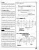
Instruction manual
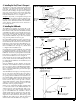
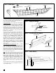
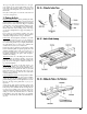

Next, check the fairness of the hull form and sand in
the slight bevels that were not pre-cut. To do this, use
a stiff basswood batten about 3/32” thick and lay it
across the bulkhead edges and deck in various loca-
tions (see figure 8). If not fair, sand the bevels that
stick out, or add shim material if there are dips. This
is an important check. The planks must lie flat
against the bulkheads without incurring any bumps
and dips on the surface. A model like the
Pride of Bal-
timore II
has many bulkheads, so it is possible for
manufacturing or assembly errors to creep in.
Critical Area:
Planks from Bulkhead “K” to the stern-
post rabbet take a severe bend. The bevel on Bulk-
head “L” is critical. Check this area thoroughly so a
batten curves smoothly from “K” over “L” and into
the sternpost rabbet. Trim “L” if necessary. This area
will require steam-bending. Otherwise, the planks
may break or buckle as they pass over Bulkhead “L”.
Option
: To avoid the possibility of a break at “L”, you
could fill the space from bulkhead “L” to the rabbet
with a solid wood block, carved to the hull curvature.
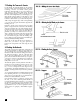
6. Installing the Transom Framing
The transom framing is composed of a filler block
port and starboard that is glued to the aft side of
Bulkhead “M” and to the center keel. On top of the
blocks you will glue six laser-cut inboard knees and
two outboard knees. The outboard knees should
slope inboard and curve on the outboard side to
catch the bulwark planking which will require a lot
of tumblehome aft near the transom.
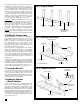
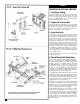
First, carve the two rectangular blocks provided in
the kit in accordance with the plans (see also figure
9). The top will need to be curved to the deck camber.
The aft side of the blocks indicate the slope and cur-
vature of the transom, and the counter below should
be a curve, but straight across. Note that the front of
each block will be exactly the same as the aft side of
Bulkhead “M”.
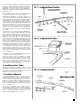
Add the laser-cut frame knees atop the carved blocks
(see figure 10). The inboard knees are straight, but the
outboard knees must be sanded to the hull curvature.
The transom will be planked later. For now, you may
want to tack a strip along the top of the knees so you
won’t accidentally break them off as you proceed.
7. Covering the Mast Slots
On both sides of the mast slots in the center keel, add
the pieces shown on the P-O-B plan. Cut from scrap
wood. Glue them securely, because you can’t get to
them after the decking is installed. The mast slots are
slightly larger than the actual mast. The mast will be
wedged in the hole when installed.
8. Installing the Planksheer
& Bulwark Stanchions
The Pride of Baltimore II has a single planksheer (or
call it a waterway). Inboard of the planksheer is a nib
-
bing strake running parallel to the planksheer. The
planksheer is provided laser-cut with holes for each
bulwark stanchion. The planksheer is 1/16” thick like
the deck planks. On the real ship, the planksheer is
slightly thicker than the deck planks (about 3/8” to
1/2”) but at 3/16” model scale this variance is not
necessary. The planksheer will be painted, so the dif-
ference will not be seen.
12
FIG. 8 – Fairing the Hull Form
FIG. 9 – Installing the Transom Framing
FIG. 10 – Adding the Frame Knees
Needs shim
(gap)
Needs trimming
(bump)
Good
Good
Heavy batten across
several bulkheads to
check fairness
Stern block
P/S
Knee (vertical)
Glue
Temporary strip
to hold knees
Outboard knee
angled inboard
BHD “M”
Stern block
Transom slope
Counter curve
Glue to “M”
BHD”M”
Deck camber curve
P/S = Port & Starboard