™ Top Flite Models Champaign, IL Telephone (217) 398-8970, Ext. 5 airsupport@top-flite.com WARRANTY SPECIFICATIONS Top Flite Models guarantees this kit to be free from defects in both material and workmanship at the date of purchase. This warranty does not cover any component parts damaged by use or modification. In no case shall Top Flite’s liability exceed the original cost of the purchased kit. Further, Top Flite reserves the right to change or modify this warranty without notice.
INTRODUCTION TABLE OF CONTENTS INTRODUCTION . . . . . . . . . . . . . . . . . . . . . . . . . 2 AMA . . . . . . . . . . . . . . . . . . . . . . . . . . . . . . . . 2 IMAA . . . . . . . . . . . . . . . . . . . . . . . . . . . . . . . 2 SCALE COMPETITION . . . . . . . . . . . . . . . . . . . . 3 SAFETY PRECAUTIONS. . . . . . . . . . . . . . . . . . . 3 DECISIONS YOU MUST MAKE . . . . . . . . . . . . . . 3 Engine Recommendations. . . . . . . . . . . . . . . 3 Radio Equipment . . . . . . . . . . . . . . . . .
of giant-scale models. If you plan to attend an IMAA event, obtain a copy of the IMAA Safety Code by contacting the IMAA at the address or telephone number below. IMAA 205 S. Hilldale Road Salina, KS 67401 Ph. (913) 823-5569 Or via the Internet at: www.fly-imaa.org/ imaa/sanction.
NOTE: Instructions for mounting every possible engine cannot be incorporated into this manual. Modelers using another engine may refer to the instructions as a guide for mounting their engine in a similar way. If using the BT-43EI-2 engine an optional muffler is recommended.
ADDITIONAL ITEMS REQUIRED REQUIRED HARDWARE AND ACCESSORIES In addition to the items listed in the “Decisions You Must Make” section, following is the list of hardware and accessories required to finish the Top Flite Giant P-47D ARF. Order numbers are provided in parentheses.
● The stabilizer and wing incidences and engine thrust angles have been factory-built into this model. However, some technically-minded modelers may wish to check these measurements anyway. To view this information visit the web site at www. greatplanes.com and click on “Technical Data.” Due to manufacturing tolerances which will have little or no effect on the way your model will fly, please expect slight deviations between your model and the published values.
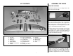
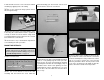
KIT CONTENTS ASSEMBLE THE WINGS HINGE THE AILERONS Start with the left wing so the assembly matches the photos the first time through. 1 22 19 12 18 9 11 8 21 17 10 20 16 13 15 3 6 5 ❏ 1. Lay 14 7 4 2 a few paper towels on top of each other and cut them into small squares. These paper towel squares will come in handy for wiping away excess epoxy throughout the assembly process (and will save you from wasting whole paper towels). ❏ ❏ 2.
the wrinkles disappear, then go over the area again, pushing down on the iron to bond the covering to the wood. If the wrinkles don’t disappear, the balsa in that area might be flexing inward. If this is happening, don’t press down. Simply let the heat of the iron shrink the covering. If the wrinkles momentarily disappear, then immediately reappear, the iron may be too hot, thus causing air bubbles.
in half and slide it over the servo connections. Shrink the tubing by applying heat to the tubing. aluminum landing gear door mounts onto the strut and reinstall the strut in the strut mount. ❏ ❏ 8. Use the string in the wing to pull the aileron wire through the wing. ❏ ❏ 9. Place the aileron servo hatch with the servo in the wing. Be certain that the hatch is positioned correctly as shown. Secure the hatches using six #2 x 3/8" [9.5mm] flat head sheet metal screws.
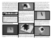
the retracts with five #6 x 3/4" [19.1mm] sheet metal screws, one in each corner and one in the middle as shown. Use one #6 x 1/2" [12.7mm] sheet metal screw in the hole over the air cylinder. ❏ ❏ 7. Remove the six screws and retract and apply a couple of drops of thin CA in the holes. ❏ ❏ 4. Extend the retract. View the wheel from directly above. Adjust the strut so that the wheel is parallel to the root of the wing.
❏ ❏ 14. Adjust the position of the two landing gear INSTALL THE FLAP SERVOS door mounts so that they align with the flats on the landing gear door when the door is positioned in the landing gear opening. ❏ ❏ 1. ❏ ❏ 15. Install a #4 flat washer on 4-40 x 3/8" [9.5mm] machine screw. Insert the machine screw through one of the holes in the gear door and thread it into the landing gear door mount. Note that it tightens against the landing gear strut before it tightens against the gear door.
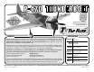
HOW TO SOLDER The Thunderbolt was a massive airplane, the biggest and heaviest single engine, single-place fighter ever built. The engine, the Pratt & Whitney 18 cylinder twin-row radial, developed 2,000 H.P. and was the most powerful engine at the time. However, in turn, it needed a highly efficient duct system for its super-charger. The designer, Alexander Kartvile, designed the duct system first, then built the fuselage around it. 1.
the wing together with rubberbands around the wing dowels and the trailing edge. ❏ 5. Remove the rubberbands and separate the wing halves. Remove the wing joiner. Mix 2 oz. [59.1cc] of 30-minute epoxy. Working quickly, pour a generous amount into the joiner pocket of one wing half. Use your wire or dowel to thoroughly distribute the epoxy, coating all surfaces inside the joiner pocket. Coat the root rib and one half of the wing joiner that goes into the wing. Insert the joiner in the wing.
ASSEMBLE THE FUSELAGE INSTALL THE STABILIZER ❏ 4. Use a sharp hobby knife to remove the covering ❏ 2. Mount each main landing gear wire in the landing gear mount with two metal straps and four #4 x 1/2" [12.7mm] sheet metal screws. from over the five mounting holes in the plywood retract cover. Set the retract cover over the retract and drill a 1/16" [1.6mm] pilot hole using the holes in the cover as a guide. ❏ 5. Mount the retract cover to the wing with five #2 x 3/8" [9.
epoxy, mixing sticks, epoxy brush, 12" [305mm] long dowel or wire, masking tape, denatured alcohol and small paper towel squares. Mix up 3/4 oz. [22.1cc] of 30-minute epoxy. Apply a generous amount of epoxy to the long side of the aluminum joiner tubes. Pull the tubes through the fuselage so that they are close to centered. Pour a small amount of epoxy into both holes of one of the stabilizer halves and using a dowel or wire, coat the inside of the holes.
❏ ❏ 10. Move the rudder left and right a few times to align the hinges and make certain that the rudder deflects left and right enough. Use a small piece of masking tape to hold the tip of the rudder in alignment with the tip of the fin. Allow the epoxy to fully cure. the three 3x6mm machine screws. Adjust the location of the steering arm so that it is flush with the top of the tail gear wire and perpendicular to the tail wheel.
❏ 6. Wrap the cable back around the swage and back through the swage. ❏ 9. ❏ 7. Use pliers to pull the cable from the first loop to reduce the size of the second loop. Retractable tail gear only: Connect 40" [1016mm] of purple air line to the forward air fitting and 40" [1016mm] of red air line to the aft fitting on the air cylinder. There is not enough air line leftover from the main gear, so additional line will have to be purchased separately (Robart #169 Pressure Tubing). ❏ 10.
INSTALL THE ELEVATOR & RUDDER SERVOS ❏ 3. Mount ❏ 1. Insert the three 4-40 x 48" [1220mm] metal pushrods in the three outer pushrod tubes shown in the photo. ❏ 2. Thread a 4-40 nut, threaded clevis and a silicone clevis retainer, 12 turns, onto both elevator pushrods and the rudder pushrod. the control horns to the elevators and the rudder. Follow the same procedure used for the ailerons, by drilling 3/32" [2.4mm] holes and using #4 x 1/2" [12.7mm] sheet metal screws.
INSTALL THE ENGINE The following engine mounting instructions shows the installation of the Fuji-Imvac BT-43EI-2 gas engine. The installation of other brands of engines will be similar and the following instructions can be used as a guide. ❏ 9. ❏ 7. Center the servo arm and the tailwheel gear. Install a swage on each cable, securing it following the same procedure used on the tail gear. Use a pliers to crimp the swage tightly on the cable. Overlap by 1" [25.
the engine to the firewall using four M5 x 30mm long and four M5 flat washers. Apply a drop of threadlocker to each bolt before installing. For reference, the distance from the front of the firewall to the front of the drive washer is 6-3/4" [171.4mm]. With the FujiImvac BT-43EI-2 one of the 1/8" [3.2mm] plywood engine spacers was required between the engine and the firewall. ❏ 4. Drill ❏ 3. Install a 2-56 ball link ball on the throttle arm of the carburetor.
as Shoe Goo® can be applied at the front to hold the tank in position, but still allow it to be removed if necessary. A plywood plate will be installed later to secure the tank at the aft end. ❏ 8. Position the throttle stick so that it is centered ❏ 10. Place on the transmitter. Adjust the throttle servo arm so that it is centered on the throttle servo. Move the throttle arm on the carburetor so that the throttle is open approximately half way. Mark and cut the white pushrod tube to length.
line from the pickup to the carburetor. The other two fuel lines can be routed out the bottom of the cowl. Insert an aluminum fuel plug in the fueling/defueling line. Secure the fuel tank in the fuselage with the two included rubberbands. a 1/16" [1.6mm] pilot hole in the hardwood rails using the two mounting tabs as guides. Attach the retract servo tray to the rails with #2 x 3/8" [9.5mm] sheet metal screws and #2 washers. ❏ 3.
❏ 8. Connect the air lines from the retracts in the wing to the quick connectors in the fuselage. Pumpup the pressure tank to the recommended pressure and operate the retracts a couple of times, making any adjustments as needed. The opening for the tail gear may need to be widened slightly at the steering arm to prevent the steering arm from rubbing on the fuselage. Tape the fiberglass tail gear retract cover over the retract opening.
❏ 2. Position the two short cowl mounting brackets in the two bottom slots in the front of the fuselage. Drill a 1/16" [1.6mm] hole through the forward former using the hole in the cowl mounting bracket as a guide. Attach the cowl mounting bracket to the forward former using 6-minute epoxy, #2 x 3/8" [9.5mm] sheet metal screws and #2 flat washers. ❏ 5. Drill 7/64" [2.7mm] holes in the bottom of the rocker arms and in the crankcase as shown. Glue the eighteen aluminum tubes in the holes. ❏ 7.
intake 3/8" [9.5mm] from the base. Trial fit the intake in the cowl. It should fit over the rocker arm covers of the radial engine, against the inner lip of the cowl. Once satisfied with the fit, use medium sandpaper to roughen the end of the intake. Clean the sanding dust off with denatured alcohol and glue it to the cowl inside with CA. Use canopy glue to attach the front of the intake to the back of the cowl lip. ❏ 9. Before gluing, use sandpaper to roughen the gluing area inside the cowl.
the covering, or trim and remove the covering from inside the outline. This will help the glue hold the fairing on. Glue the turbocharger exhaust fairing on the fuselage with canopy glue or medium CA. ❏ 16. Use a piece of stiff card stock or a file folder taped to the side of the fuselage to mark the location of the ignition switch. ❏ 18. Follow the same procedure for the muffler, cooling air exit and the carburetor air intake if the Fuji-Imvac BT-43EI-2 has been installed.
the red round headed pins in the lower right corner of the instrument panel to represent a knob. Glue the instrument panel in the front of the cockpit so that the top of the instrument panel is flush with the top of the fuselage. Canopy glue or thick CA works well for attaching the instrument panel. ❏ 4. Trim the armor plate and the cockpit floor along the edge so that they lay flat. Use medium CA to glue the floor in the bottom of the cockpit. The floor should be positioned as far forward as possible.
pan on the bottom of the wing. Cut and remove a 1/2" [12.7mm] wide strip of covering, 1/32" [0.8mm] from inside the outline. ❏ 4. The “bubble canopy” version was a result of pilots’ complaints of lack of rearward visibility. In 1943 a P-47D-5 was modified by removing the razor spine and fitting a modified Hawker Tempest bubble canopy. In addition to the new canopy was a flat, armored windscreen.
6-minute epoxy. Note the distance from the leading edge of the wing to the end of each gun barrel. Please use the following pictures as a guide for decal placement. The “belly pan” under the wing conceals the air ducting for the supercharger. One duct carries air from the intake in the front of the cowl back to the supercharger (driven by the turbine) and two smaller ducts carry exhaust gasses from the engine to the turbine. APPLY THE DECALS ❏ 1.
GET THE MODEL READY TO FLY 4-CHANNEL RADIO SETUP (STANDARD MODE 2) INSTALL THE PROPELLER ❏ 1. Carefully balance the propeller and any spare propellers. An unbalanced propeller can be the single most significant cause of vibration that can damage the model. Not only will engine mounting bolts loosen, possibly with disastrous effect, but vibration may also damage the receiver and receiver batteries. Vibration can also cause the fuel to foam, which will, in turn, cause the engine to run hot and quit.
NOTE: The throws are measured at the widest part of the elevators, rudder and ailerons. At the Servos The pushrod closer in means Less Throw At the Control Surfaces AILERONS The pushrod closer in means More Throw FLAPS ❏ 1. Use a box or something similar to prop up the bottom of the fuselage so the horizontal stabilizer and wing will be level. Hold a ruler vertically on your workbench against the widest part (front to back) of the trailing edge of the elevator. Note the measurement on the ruler.
At this stage the model should be in ready-to-fly condition with all of the components in place including the complete radio system, engine, muffler, propeller, spinner and pilot. The fuel tank should be empty. 6-3/8" [162mm] at least 10"[254mm] to prevent ignition noise from interfering with the radio system. If the plane is nose heavy, do not move the receiver battery forward closer to the ignition system. If the plane is tail heavy, do not move the ignition battery aft closer to the receiver. ❏ 4.
❏ 9. Reinforce holes for wood screws with thin CA where appropriate (servo mounting screws, cowl mounting screws, etc.). ❏ 10. Confirm that all controls operate in the correct direction and the throws are set up according to the manual. ❏ 11. Make sure there are silicone retainers on all the clevises and that all servo arms are secured to the servos with the screws included with your radio. ❏ 12.
GENERAL 1) I will not fly my model aircraft in sanctioned events, air shows, or model flying demonstrations until it has been proven to be airworthy by having been previously, successfully flight tested. 2) I will not fly my model aircraft higher than approximately 400 feet within 3 miles of an airport without notifying the airport operator. I will give right-of-way and avoid flying in the proximity of full-scale aircraft.
aircraft presents a greater danger than an overpowered aircraft. However, the selection of engine size relative to airframe strength and power loading mandates good discretionary judgment by the designer and builder. Current AMA maximums for engine displacement are 6.0 cu. in. for two-stroke and 9.6 cu. in. for four-stroke engine. These maximums apply only to AMA Sanctions concerning competition events (such as 511, 512, 515 and 520) and, as such, the maximums apply.
Have a ball! But always stay in control and fly in a safe manner. GOOD LUCK AND GREAT FLYING! Note: If ever the occasion arises when a dead-stick landing must be performed, do not extend the flaps until certain the model will be able to reach the landing zone 36 AMA Number Phone Number GEAR DOOR DRILL GUIDE City, State, Zip The Giant P-47D ARF may be landed with or without flaps.