
Specifications

11
❏
❏
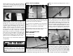
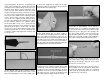
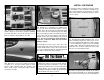
14. Adjust the position of the two landing gear
door mounts so that they align with the fl ats on the
landing gear door when the door is positioned in the
landing gear opening.
❏
❏
15. Install a #4 fl at washer on 4-40 x 3/8"
[9.5mm] machine screw. Insert the machine screw
through one of the holes in the gear door and
thread it into the landing gear door mount. Note that
it tightens against the landing gear strut before it
tightens against the gear door. Install the second
machine screw to hold the gear door in position.
Check to make sure that the gear door is fl ush with
the bottom of the wing. 1.5mm thick rectangular
plywood spacers have been included to space the
gear doors out if needed. Both screws will need to
be shortened, a little at a time, so that they tighten
against both the landing gear strut and the gear
door. Be sure to use threadlocker on the screws.
❏
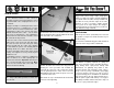
16. Return to step 1 and mount the right retract in
the right wing.
The P-47 was manufactured by Republic Aircraft
Corporation, which at one time was named
Seversky Aircraft Corporation, started by two fellow
Russians, Alexander De Seversky and Alexander
Kartveli.
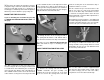
INSTALL THE FLAP SERVOS
❏
❏
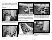
1. Install the fl ap servos following the same
procedure used to install the aileron servos. Note that
the fl ap servos face the same direction.
❏
❏
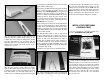
2. Connect a 12" [305mm] servo extension wire
to the fl ap servo. Secure the extension to the servo
with a piece of heat shrink or electrical tape.
❏
❏
3. Route the fl ap servo leads to the root of the
wing and out the hole in the top of the wing.
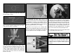
INSTALL THE AILERON AND
FLAP PUSHRODS
Do the left aileron fi rst.
❏
❏
1. Slide a silicone clevis retainer over a 4-40
threaded metal clevis. Thread a 4-40 nut followed by
the 4-40 metal clevis, threaded 12 turns onto a 4-40
x 12" [305mm] metal pushrod. Attach the clevis to the
aileron servo arm 5/8" [15.9mm] from the center of
the arm.
❏
❏
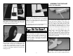
2. Position the control horn so that it is inline
with the pushrod and over the plywood mounting
plate. The pushrod holes in the control horn should
be aligned with the hinge line of the aileron. On the
aileron, mark the four mounting holes. Remove the
control horn and drill a 5/64" [2mm] pilot hole at each
mark. Do not drill completely through the aileron.
Attach the control horn using four #4 x 1/2" [12.7mm]
sheet metal screws. Use thin CA to harden the holes.
❏
❏
3. Install the metal solder clevis in the second
hole from the end of the control horn. Center the
aileron servo and aileron. Mark the pushrod where it
meets the solder clevis. Remove the pushrod and the
solder clevis and cut the pushrod 1/4" [6.4mm] past
the mark. Solder the solder clevis to the pushrod using
the techniques described in the following Hot Tip.