
Specifications

12
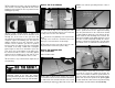
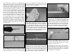
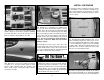
HOW TO SOLDER
1. Use denatured alcohol or other solvent to
thoroughly clean the pushrod. Roughen the end of
the pushrod with coarse sandpaper where it is to
be soldered.
2. Apply a few drops of soldering fl ux to the end of
the pushrod, then use a soldering iron or a torch
to heat it. “Tin” the heated area with silver solder
by applying the solder to the end. The heat of the
pushrod should melt the solder – not the fl ame
of the torch or soldering iron – thus allowing the
solder to fl ow. The end of the wire should be coated
with solder all the way around.
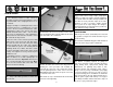
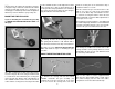
3. Place the clevis on the end of the pushrod. Add
another drop of fl ux, then heat and add solder.
The same as before, the heat of the parts being
soldered should melt the solder, thus allowing
it to fl ow. Allow the joint to cool naturally without
disturbing. Avoid excess blobs, but make certain
the joint is thoroughly soldered. The solder should
be shiny, not rough. If necessary, reheat the joint
and allow to cool.
4. Immediately after the solder has solidifi ed, but
while it is still hot, use a cloth to quickly wipe off
the fl ux before it hardens. Important: After the joint
cools, coat the joint with oil to prevent rust. Note:
Do not use the acid fl ux that comes with silver
solder for electrical soldering.
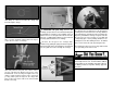
This is what a properly soldered clevis looks
like – shiny solder with good flow, no blobs and
flux removed.
❏
❏
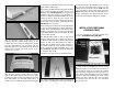
4. Slide a silicone clevis retainer over the solder
clevis. Reinstall the aileron pushrod with the threaded
clevis attached to the control horn.
❏
❏
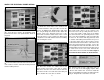
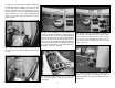
5. Assemble and connect the fl ap pushrods
following the same procedure. We installed the
pushrod in the outer hole of the control horn and the
hole 3/8" [9.5mm] from the center of the servo arm.
Note: With the fl ap fully retracted “up”, the servo arm
is centered on the servo.
❏
6. Return to step 1 and install the aileron and fl ap
pushrods on the right wing.
The Thunderbolt was a massive airplane, the
biggest and heaviest single engine, single-place
fi ghter ever built. The engine, the Pratt & Whitney
18 cylinder twin-row radial, developed 2,000 H.P.
and was the most powerful engine at the time.
However, in turn, it needed a highly effi cient
duct system for its super-charger. The designer,
Alexander Kartvile, designed the duct system fi rst,
then built the fuselage around it.
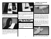
JOIN THE WING
Note: Keep the retracts (if installed) in the retracted
(up) position so they do not extend and retract as you
handle the wing.
❏
1. Clean the aluminum wing joiner with denatured
alcohol to remove any possible contaminant.
❏
2. Gather everything required for gluing the
wing joiner and wing together including 30-minute
epoxy, mixing sticks, epoxy brush, clamps, #64
rubberbands, 12" [305mm] long dowel or wire,
denatured alcohol and small paper towel squares.
Mix up a 1/2" oz. [14.7cc] of 30-minute epoxy. Apply
a generous amount of epoxy to one side of each of
the plywood wing joiners. Sandwich the aluminum
wing joiner between the two plywood wing joiners.
Hold the joiner together with clamps. Use a paper
towel dampened with denatured alcohol to wipe off
any excess epoxy around the edges.