
Specifications
16
❏
❏
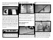
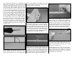
10. Move the rudder left and right a few times
to align the hinges and make certain that the rudder
defl ects left and right enough. Use a small piece of
masking tape to hold the tip of the rudder in alignment
with the tip of the fi n. Allow the epoxy to fully cure.
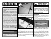
MOUNT THE FIXED TAIL GEAR
If you are installing the retractable tail gear, skip
to “MOUNT THE RETRACTABLE TAIL GEAR” on
this page.
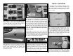
❏
1. Slide a 3.5mm wheel collar on the tail gear wire.
Insert the tail gear wire in the tail gear mount. Install
a second wheel collar followed by the steering arm
on the tail gear wire. Apply a drop of threadlocker on
three 3x6mm machine screws. Secure the two wheel
collars and the steering arm to the tail gear wire with
the three 3x6mm machine screws. Adjust the location
of the steering arm so that it is fl ush with the top of
the tail gear wire and perpendicular to the tail wheel.
Also, remove the two nuts from the top of the tail gear,
apply threadlocker and reinstall the nuts.
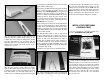
❏
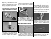
2. Enlarge the holes in the steering arm with a
5/64" [2mm] drill bit. Mount a 2-56 ball link ball to
each arm with a 2-56 nut and a drop of threadlocker.
❏
3. Skip to step 5 in “Mount the Retractable Tail
Gear” and follow the steps for installing the pull-
pull cable.
MOUNT THE RETRACTABLE TAIL GEAR
❏
1. Remove the steering arm from the Robart
#160LWC retractable tail gear assembly (not
included). File a fl at spot near the top of the shaft
for the set screw in the steering arm to lock onto.
Mount the steering arm to the shaft with a drop of
threadlocker and the set screw.
❏
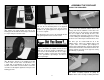
2. File another fl at spot near the bottom of the
shaft for one of the set screws in the strut. Tighten
both set screws with a drop of threadlocker on each.
Be certain the steering arm and the axle in the strut
remain parallel with each other. Make adjustments to
the fl at spots if necessary.
❏
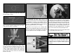
3. Enlarge the hole through the 1-3/4" [44mm] tail
wheel with a #9 [5mm] drill. Cut the axle included with
the Robart retractable tail gear to the correct length,
then fi le a fl at spot on it and mount it to the strut.
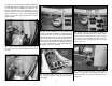
❏
4. Enlarge the middle hole in both sides of the
steering arm with a 3/32" [2.4mm] drill. Insert a 2-56
ball link ball in the hole. Secure each ball with a 2-56
nut and a drop of threadlocker.
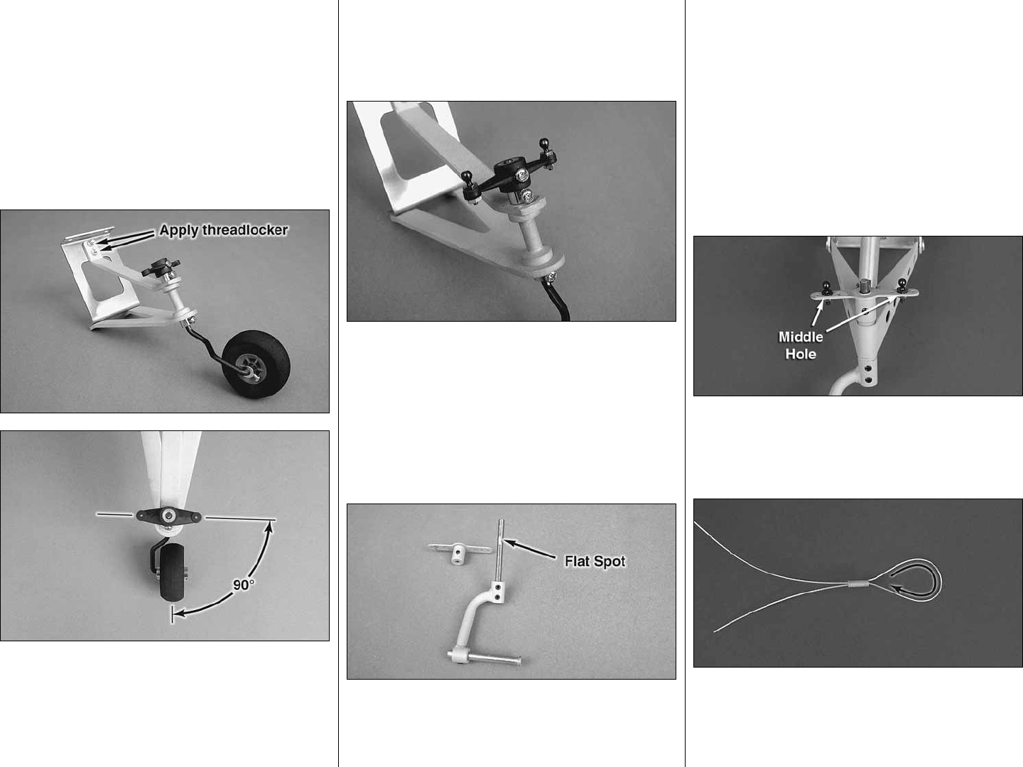
❏
5. Use wire cutters to cut the supplied braided
cable into two equal lengths. Slide a small copper
tube (called a swage) over one end of the cables,
then guide the end of the cable back through.