
Specifications

18
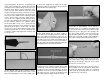
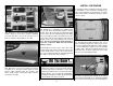
INSTALL THE ELEVATOR & RUDDER SERVOS
❏
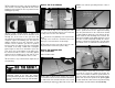
1. Insert the three 4-40 x 48" [1220mm] metal
pushrods in the three outer pushrod tubes shown in
the photo.
❏
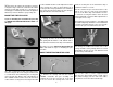
2. Thread a 4-40 nut, threaded clevis and a silicone
clevis retainer, 12 turns, onto both elevator pushrods
and the rudder pushrod.
❏
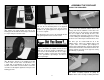
3. Mount the control horns to the elevators and
the rudder. Follow the same procedure used for the
ailerons, by drilling 3/32" [2.4mm] holes and using
#4 x 1/2" [12.7mm] sheet metal screws. Attach the
elevator clevis in the third hole from base of the
control horn. Install the rudder clevis in the second
hole from the base of the control horn. Don’t forget
to harden the holes with thin CA after fi rst installing,
then removing the screws.
❏
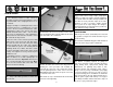
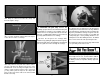
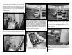
4. Place two elevator, one rudder and one tail
wheel steering servo in the servo tray as shown.
Make three one-arm servo arms and one two-arm
servo arm from the servo arms that came with your
servos. Position the servo arms as shown.
❏
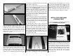
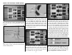
5. Install solder clevises on the elevator servo
arms in the hole 7/16" [11.1mm] from the center of
the servo arm. Install a solder clevis on the rudder
servo arm in the hole 1/2" [12.7mm] from the center
of the servo arm. Following the same procedure that
was done for the aileron and fl ap pushrods, mark
the elevator and rudder pushrods where they are to
be cut for the solder clevises. One at a time, remove
the threaded metal clevis from the control horn end,
remove the pushrod from the fuselage, cut it to the
correct length and solder a metal solder clevis on the
end. Reinstall the pushrod from the front and connect
the solder clevis to the servo arms. Reinstall the
threaded metal clevis and 4-40 nut. Don’t forget to
use a silicone clevis retainer on all the clevises.
❏
6. Thread a 4-40 nut and a 4-40 metal clevis, 12
turns, on to each of the 4-40 rigging couplers. Slide
a silicone clevis retainer over each clevis. Install the
clevises on the tailwheel steering servo arm in the holes
7/16" [11.1mm] from the center of the servo arm.