
Specifications
19
❏
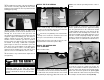
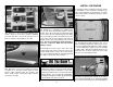
7. Center the servo arm and the tailwheel gear.
Install a swage on each cable, securing it following
the same procedure used on the tail gear. Use a
pliers to crimp the swage tightly on the cable.
❏
8. Mount the receiver on/off switch and charge
receptacle in a strategic location where it won’t
interfere with anything inside the fuselage and
where it will not get coated with engine exhaust
outside the fuselage.
❏
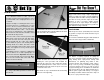
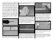
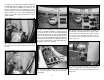
9. Overlap by 1" [25.4mm] a 6" [152mm] long
piece of hook and a 6" [152mm] long piece of loop
material. Route the hook and loop material through
the two slots in the left forward fuselage side. Wrap
your receiver battery in R/C foam rubber and secure
it to the side of the fuselage with the hook and loop
material. Connect the receiver battery to the receiver
switch. Use the included heat shrink material to
secure the connectors. Make sure the receiver
battery is secure.
❏
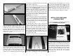
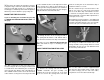
10. Mount the receiver on the other side of the
fuselage using hook and loop material. Connect the
receiver switch and the servos to the receiver. Route
the receiver antenna through the remaining pushrod
tube. Attach a strain relief on the antenna.
Early production Thunderbolts were not without
teething pains typical of any new aircraft. Takeoff
runs were long (nearly a half-mile to clear a fi fty
foot obstacle) and there were several electrical and
hydraulic glitches, not to mention the unfamiliarity
of a totally new design. One fi ghter group damaged
or wrecked half of the P-47s received.
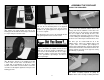
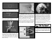
INSTALL THE ENGINE
The following engine mounting instructions shows
the installation of the Fuji-Imvac BT-43EI-2 gas
engine. The installation of other brands of engines
will be similar and the following instructions can be
used as a guide.
❏
1. The Giant P-47 ARF fi rewall has two sets of
engine mounting bolt patterns embossed on it. The
“X” is for the Fuji-Imvac BT-43EI-2 gas engine and the
“+” is for the DA-50 gas engine. If you are installing
an engine with a different mounting bolt pattern the
fi rewall also has crosshairs embossed on it to help
locate the correct mounting location.
❏
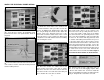
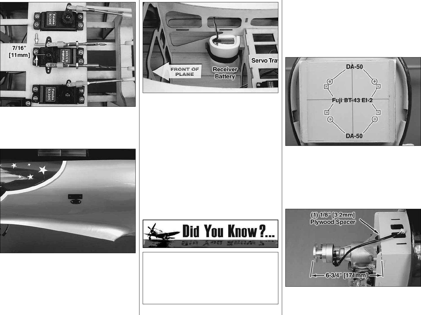
2. Drill a 1/4" [6.4mm] hole through the fi rewall at
each location marked with an “X”. Install the M5 blind
nuts in the holes from the back of the fi rewall. Mount