
Specifications


20
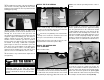
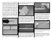
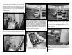
the engine to the fi rewall using four M5 x 30mm long
and four M5 fl at washers. Apply a drop of threadlocker
to each bolt before installing. For reference, the
distance from the front of the fi rewall to the front of
the drive washer is 6-3/4" [171.4mm]. With the Fuji-
Imvac BT-43EI-2 one of the 1/8" [3.2mm] plywood
engine spacers was required between the engine
and the fi rewall.
❏
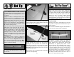
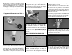
3. Install a 2-56 ball link ball on the throttle arm of
the carburetor. Secure the ball link ball with a 2-56
lock nut.
❏
4. Drill a 3/16" [4.8mm] hole inline with the ball
link ball. Use medium sandpaper to roughen the gray
outer pushrod tube. Clean the tube with denatured
alcohol and insert the tube into the previously drilled
hole in the fi rewall. Route the tube through the front
formers of the fuselage until it protrudes approximately
1/8" [3mm] from the fi rewall. Use thin CA to glue the
tube to the fi rewall. Trim the tube approximately 1"
[25.4mm] in front of the servo tray.
❏
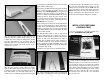
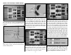
5. Mount the throttle servo in the servo tray and
slide a plywood pushrod support onto the outer
pushrod tube.
❏
6. Thread a 2-56 x 1" [25.4mm] threaded rod
approximately 3/8" [9.5mm] into the end of the white
inner pushrod tube. Thread a nylon clevis 14 turns
onto the end of the threaded rod. Slide a silicone
clevis retainer over the clevis. Attach the clevis to the
throttle servo arm.
❏
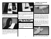
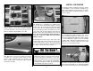
7. Thread the nylon ball link socket 14 turns
onto the second 2-56 x 1" [25.4mm] threaded rod.
Attach the ball link socket to the ball link ball on the
throttle arm.