
Specifications


21
❏
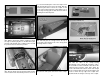
8. Position the throttle stick so that it is centered
on the transmitter. Adjust the throttle servo arm so
that it is centered on the throttle servo. Move the
throttle arm on the carburetor so that the throttle
is open approximately half way. Mark and cut the
white pushrod tube to length. Remove the ball link
socket from the throttle arm and thread it into the cut
end of the white pushrod tube. Reattach the clevis
to the throttle servo arm and the ball link socket to
the ball link ball. Make adjustments as needed so
that the throttle opens and closes completely. Glue
the plywood pushrod support to the second former
and the outer pushrod tube to the support. If needed
a second pushrod support could be glued to the
fuselage side, closer to the throttle servo.
❏
9. Install the servo operated choke following the
same procedure.
❏
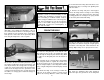
10. Place the ignition module on a piece of R/C
foam rubber and secure it to the top of the fi rewall
box with hook and loop material. Rubber straps, cut
from a rubberband (not included) can be glued to the
fi rewall box to hold the excess wires.
❏
11. Wrap the ignition battery in R/C foam rubber
and attach it to the bottom of the fi rewall box with hook
and loop material. The ignition switch can be installed
in the fuselage side at this time or a separate switch
mount has been provided that mounts to the side of
the fi rewall box. The switch can be accessed through
a hole in the cowl.
ASSEMBLE AND INSTALL
THE FUEL TANK
❏
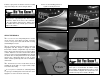
1. Attach a 12" [305mm] piece of airline tubing to
the pressure tank. Insert the pressure tank into the
fuselage. A couple of dabs of silicone sealant such
as Shoe Goo
®
can be applied at the front to hold
the tank in position, but still allow it to be removed if
necessary. A plywood plate will be installed later to
secure the tank at the aft end.
❏
2. Assemble the fuel tank stopper assembly with
the fuel tubes as shown. The easiest way is to fi rst
solder a fuel line barb (not included) onto one end
of all three tubes. Insert the tubes into the stopper
with the metal plates, and then solder a barb onto
the other end of the two short tubes. Bend the vent
tube and connect the pickup and fueling/defueling
lines (not included) to the short tubes. Connect the
clunks to the lines and secure the lines to the clunk
and brass tubing with the included small tie straps.
❏
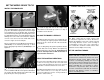
3. Install the fuel tank stopper assembly in the
fuel tank. Check that the clunks move around freely
in the fuel tank. Tighten the fuel tank stopper screw.
Refer to step 5 on page 22 for the orientation of the
fuel tank.