
Specifications


23
❏
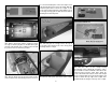
6. Cut off 1/2" [12.7mm] from the threaded end
of the 2-56 x 6" [152mm] metal pushrod. Thread the
nylon ball socket on the pushrod. Snap the ball socket
onto the ball link ball on the retract control valve. Mark
the pushrod where it crosses the servo arm and make
a 90 degree bend at the mark. Install the pushrod in
the servo arm and install a nylon FasLink. Cut the
pushrod 1/8" [3mm] past the top of the FasLink.
❏
7. Install a fi ll valve in the fuselage side in
a convenient location. Refer to the air retracts
instructions. Connect the pressure tank, fi ll valve and
control valve to a T-fi tting. Connect the two air lines
coming from the tail gear retract to separate T-fi ttings.
Then, connect the T-fi ttings to the control valve.
Finally connect the quick connects to the T-fi ttings.
Make sure the quick connectors correspond to the
quick connectors installed in the wing. Electrical tape
can be used to wrap the air lines together to clean up
the installation.
❏
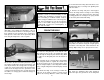
8. Connect the air lines from the retracts in the
wing to the quick connectors in the fuselage. Pump-
up the pressure tank to the recommended pressure
and operate the retracts a couple of times, making any
adjustments as needed. The opening for the tail gear
may need to be widened slightly at the steering arm to
prevent the steering arm from rubbing on the fuselage.
Tape the fi berglass tail gear retract cover over the
retract opening. Again, operate the retracts, checking
that the tail gear retract does not hit the cover.
❏
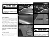
9. The tail gear retract cover can be permanently
installed using CA glue or with screws. If CA glue is
used it will be diffi cult to remove the cover and access
the retracts if needed. To install the cover with screws,
tape a piece of paper to the fuselage at each corner
of the tail gear opening. Place a mark on the paper
at the center of the stringer. Reposition the retract
cover and tape it in place. Drill 1/16" [1.6mm] holes
through the cover and the stringers at each mark.
Remove the cover and enlarge the holes in the cover
only with a 3/32" [2.4mm] drill bit. Attach the cover
to the fuselage with #2 x 3/8" [9.5mm] sheet metal
screws and #2 washers. Harden the screw holes with
thin CA glue.
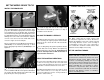
One might question the selection of an older
technology, bulkier radial engine vs. a more
modern and streamlined “V” engine for the P-47. A
problem of “V” engines is their liquid cooling system
(including a radiator) which is susceptible to gun
fi re. Before Glycol became available, liquid cooled
engines also featured extremely large radiators
adversely affecting aerodynamics. Early P-47
design team members were not willing to “put all
their eggs in one basket” and utilized “V” engines
for some of their other projects.
INSTALL THE COWL
❏
1. Note that there are four long cowl mounting
brackets and two short cowl mounting brackets.