
Specifications


25
❏
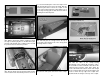
9. Before gluing, use sandpaper to roughen the
gluing area inside the cowl. Clean the area with a
paper towel dampened with denatured alcohol. Mix
approximately 1/2 oz [14.7cc] of 30-minute epoxy.
For a stronger joint, add some milled fi berglass to the
epoxy. Apply epoxy to the edge of the engine assembly
and insert it in the cowl. Use the remaining epoxy to
create a fi llet around the edge of the assembly.
❏
10. Trim the red turbo charger/oil cooler intake
around the base. Then mark and trim the top of the
intake 3/8" [9.5mm] from the base. Trial fi t the intake
in the cowl. It should fi t over the rocker arm covers
of the radial engine, against the inner lip of the cowl.
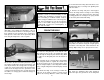
Once satisfi ed with the fi t, use medium sandpaper
to roughen the end of the intake. Clean the sanding
dust off with denatured alcohol and glue it to the cowl
inside with CA. Use canopy glue to attach the front of
the intake to the back of the cowl lip.
❏
11. Test fi t the cowl over the engine. Install the
recommended propeller on the engine. Adjust the
position of the cowl so that the dummy radial engine
is centered on the drive washer and the propeller
clears the front of the cowl by 1/8" [3.2mm]. The cowl
mounting brackets should be approximately 1/8"
[3.2mm] inside the edge of the cowl.
❏
12. The six cowl mounting brackets can be seen
from the rear of the cowl. Drill a 3/32" [2.4mm] pilot
hole through the cowl and the center of the cowl
mounting brackets. Enlarge the holes in the cowl
to 1/8" [3.2mm]. Secure the cowl to the mounting
brackets with #4 x 1/2" [12.7mm] sheet metal screws
and #4 fl at washers. Be sure to harden the screw
holes with thin CA.
❏
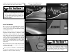
13. Assemble the ignition switch bracket as shown.
Note that the tabs on the sides, top and bottom should
all be at the same end.
❏
14. Attach the switch bracket to the side of the
fi rewall box with 6-minute epoxy and two #2 x 3/8"
[9.5mm] sheet metal screws and #2 fl at washers.
Coat the switch bracket with thinned epoxy or fuel
proof paint after it is installed.
❏
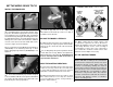
15. Install the ignition switch in the switch bracket.
Connect the switch to the ignition battery and the
ignition module. Use heat shrink to help secure the
connections. As with the ignition wires, pieces of
rubberbands can be glued to the fi rewall box, over
the ignition switch wires to hold them in position.