
Specifications


26
❏
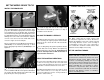
16. Use a piece of stiff card stock or a fi le folder
taped to the side of the fuselage to mark the location
of the ignition switch.
❏
17. With the card stock still taped to the fuselage,
re-install the cowl. Make the switch location, remove
the cowl and cut the opening for the ignition switch
in the side of the cowl using a high speed rotary tool
with a carbide cutting bit. Start with a small hole and
slowly enlarge the hole, while test fi tting the cowl on
the fuselage.
❏
18. Follow the same procedure for the muffl er,
cooling air exit and the carburetor air intake if the
Fuji-Imvac BT-43EI-2 has been installed. Remove
the cowl before cutting the holes to prevent fi berglass
dust from entering the carburetor. Route the fuel/
defuel and vent fuel lines out the cooling air exit in
the bottom of the cowl. Install the aluminum fuel line
plug in the fuel/defueling line.
APPLY THE FINAL DETAILS
❏
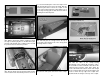
1. Position the turbocharger exhaust fairing as
shown. Mark on the fuselage the outline of the fairing.
Inside the outline use a T-pin to prick small holes in
the covering, or trim and remove the covering from
inside the outline. This will help the glue hold the
fairing on. Glue the turbocharger exhaust fairing on
the fuselage with canopy glue or medium CA.
❏
2. Glue the two innercooler exhaust doors in the
two cutouts in the aft end of the fuselage.
❏
3. Glue the two oil cooler louvers to the forward
lower fuselage following the same procedure used to
install the turbocharger exhaust fairing.