
Specifications

9
in half and slide it over the servo connections. Shrink
the tubing by applying heat to the tubing.
❏
❏
8. Use the string in the wing to pull the aileron
wire through the wing.
❏
❏
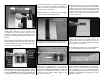
9. Place the aileron servo hatch with the servo
in the wing. Be certain that the hatch is positioned
correctly as shown. Secure the hatches using six #2
x 3/8" [9.5mm] fl at head sheet metal screws. Use thin
CA to harden the screw threads.
❏
10. Go back to step 1 and install the right aileron
servo following the same procedure.
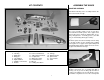
MOUNT THE RETRACTS
Note: The fi xed main landing gear will not be
installed until after the two wing halves have been
joined. If using the fi xed main landing gear, proceed
to “Install the Flap Servos” on page 13.
Install the left retract fi rst.
❏
❏
1. Use a hex wrench to loosen the strut
mounting bolt and remove the strut. Slide two
aluminum landing gear door mounts onto the strut
and reinstall the strut in the strut mount.
❏
❏
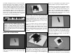
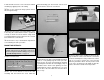
2. Trim the axle that is included with the Robart
retracts to 1-1/2" [38mm] long. File a fl at spot at the
end of the axle. Insert the axle through the included
5" [127mm] wheel and into the retract. Apply a drop of
threadlocker to the 10-32 x 3/16" [4.8mm] set screw,
included with the retract, and tighten the set screw
onto the fl at of the axle. Make sure that the wheel
rotates freely.
❏
❏
3. Test fi t the retract unit with the wheel into the
wing. Position the retract so the wheel is centered in
the wheel well. Adjust the strut position in the retract
body as necessary to achieve the correct spacing
all the way around the wheel. You may need to sand
the top of the opening in the rib slightly to allow the
retract to fi t. Remove as little wood as possible.