LANDSCAPE FULLVIEW SERIES LFV4015-SH • LFV6015-SH• LFV8015-SH LFV10015-SH • LFV12015-SH SAFETY INFORMATION AND OPERATIONS MANUAL Read these instructions completely before beginning installation. Failure to follow them could cause a heater malfunction resulting in serious injury and/or property damage. WARNING: All electric heaters have hot and arcing or sparking parts inside. Do not use it in areas where gasoline, paint or flammable liquids are or are stored.
USER INSTRUCTIONS TABLE OF CONTENTS Important Instructions .................................. 2 Power Data .................................................. 3 Product Guide ............................................. 4 Box Contents ............................................... 4 Locating Fireplace ....................................... 5 Installation ................................................... 6 Operation ................................................... 9 Service Parts ....................
USER INSTRUCTIONS IMPORTANT INSTRUCTIONS Return heater to authorized service facility for examination, electrical or mechanical adjustment, or repair. 12. This heater is not intended for use in bathrooms, laundry areas and similar indoor locations. Never locate heater where it may fall into a bathtub or other water container. 13. Do not run cord under carpeting. Do not cover cord with throw rugs, runners, or the like. Arrange cord away from traffic area and where it will not be tripped over. 14.
USER INSTRUCTIONS PRODUCT GUIDE 1/2 inch Drywall Stop x4 L Metal Nailing Flanges 22.
INSTALLATION LOCATING FIREPLACE CAUTION: Do not locate in a moist room such as a bathroom or laundry room. CAUTION: Wear gloves and safety glasses for protection during installation and maintenance. INSTALLATION WARNING: If the information in these instructions is not followed exactly, a fire or explosion may result causing property damage, personal injury or death. WARNING - RISK OF FIRE! To prevent a possible fire, do not block air intake or exhaust in any manner.
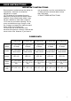
INSTALLATION Model H W D LFV4015-SH 23” 55 3/4” 12” LFV6015-SH 23” 75 3/4” 12” LFV8015-SH 23” 95 3/4” 12” LFV10015-SH 23” 115 3/4” 12” LFV12015-SH 23” 135 3/4” 12” 1. Prepare the framed opening according to the chart above.. Provide a flexible 15 amp 120 volt circuit for hard wire installation. 2. Install L Metal Nailing Flanges. H D W To be performed by a qualified electrician according to local building codes 3. Connect hard wire to the terminal block.
INSTALLATION 4. Install the fire unit in the framed opening with a minimum 1 ¼ drywall screws to secure the unit. 5. Mask the exposed fire unit during the drywall process. Install drywall to the drywall stops on the perimeter of the fire insert. For more information on the drywall stops see the Product Guide on page 4. Decorate as desired. 6. After installation, user may elect to use the L Metal Deco Trim. To install, use a small amount of construction adhesive and secure to the drywall face.
INSTALLATION Optional installations: Installing remote touch control 1. Locate and remove the access door on the rear right side of the fire unit. 2. Locate the remote touch control directly inside the access panel. Pull the touch control through the access panel and replace the access door. Locate the touch control anywhere within cable length. Installing a fire feature (Canyon Juniper Log set, Crystal Glass Coal set) 1.
OPERATION OPERATION The unit is hardwired and has no main switch. (Caution: If servicing this unit, turn off power at the main circuit breaker.) An optional tethered wall control switch is included, refer to installation instructions to relocate the tethered wall control switch to a wall location. Power When all indicator lights are off, touching any button will only show the status. Once the indicator lights are on you can begin operation. Touch the power button to turn the machine on.
MAINTENANCE LANDSCAPE SERVICE PARTS ITEM PHOTO COMMENTS MFPCB1 PRINTED CIRCUIT BOARD CONTROLS LOW VOLTAGE AND HIGH VOLTAGE FUNCTIONS MFTC1 LCD TOUCH CONTROL MFRR1 REMOTE CONTROL IR RECEIVER MF12VT1 TRANSFORMER MFHF12015-RH HEATER FAN 120 V 1500 WATTS RIGHT HAND MFHF12015-LH HEATER FAN 120 V 1500 WATTS LEFT HAND MFPHF AL HEATER 120 V 750 WATTS MFSM120 SPINDLE MOTOR 120 V 50-60 HZ MFPLS40 LED LED LIGHT STRING LS 40 MFPLS60 LED LED LIGHT STRING LS 60 MFPLS80 LED LED LIGHT STRING LS 80
MAINTENANCE FREQUENTLY ASKED QUESTIONS Q. How do you program the remote control? A. The remote comes pre-programmed. No programming is necessary. Q. What distance can the remote be used from the fireplace? A. Optimal distance for the remote control is within 10 yards. Q. Can you turn on the fireplace via the touch screen and off via the remote (or vise versa)? A. Yes. Q. Low long will the LED lights last? A. LED Lamps have a life span of up to 20 years. Q.
MAINTENANCE PROBLEM POSSIBLE CAUSE CORRECTIVE ACTION A. Breaker tripped or circuit has no A. Reset breaker, test circuit for power power B. Internal component is frozen Nothing comes on (touch and needs to be reset screen, etc.) C. Defective component B. Turn power off at the main breaker for 20 seconds. Turn power back on. C. Qualified service technician needs to replace motherboard, transformer or LCD touch control A. Reposition the fireplace in the A.
MAINTENANCE PROBLEM Heater does not provide heat when on POSSIBLE CAUSE CORRECTIVE ACTION A. Wiring is loose A. Disconnect unit from power source and inspect for loose connections B. Thermal snap disc has been tripped B. Turn the main breaker to the “off” position for 30 seconds. Next flip the breaker back into the “on” position. C. Heater core is defective C. Replace Heater Core CLEANING AND MAINTENANCE INSTRUCTIONS There is very little maintenance involved with your electric fireplace.
MAINTENANCE NOTES 14
MAINTENANCE NOTES 15
© 2013 www.modernflames.com Please dispose of properly.