Renegade Installation Instructions works with the Google Assistant
Please read and save these instructions before installation DO NOT RETURN TO STORE 2 Renegade Instructions FR-W2001
General Inquiries For all questions about your ceiling fan please read all included instructions, installation procedures, troubleshooting guidelines and warranty information before starting installation. For missing parts or general inquiries call our trained technical staff at: 1-866-810-6615 option 0 MON-FRI 8AM-8PM EST Email: customerservice@modernforms.com Or live chat at modernforms.com Fan Support For fast service have the following information below when you call: 1. Model Name and Number 2.
Safety Rules For operation, maintenance, and troubleshooting information, visit http://modernforms.com/fan-support/ To reduce the risk of electric shock, ensure electricity has been turned off at the circuit breaker before beginning. All wiring must be in accordance with the National Electrical Code “ANSI/NFPA 70” and local electrical codes. Electrical installation should be performed by a licensed electrician. The fan must be mounted with a minimum of 7 ft. (2.
WARNING: Do not install or use your fan if any part(s) is/are damaged or missing. This product is designed for use only with the supplied parts and/or accessories designated for use with this product by Modern Forms. Substitution of parts or accessories not designated for use with this product by Modern Forms could result in personal injury or property damage and will void the warranty. Contact an authorized dealer or the manufacturer if any parts are damaged or missing.
Get Smart... works with the Google Assistant Integrates seamlessly with: devices you already own Wet Location-listed to the strictest UL/cUL safety regulations.
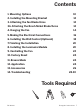
Contents 1. Mounting Options 10 2. Installing the Mounting Bracket 12 3. Attaching the Fan Blade/Arms 12 3A. Attaching the Brush Nickel Blade/Arms 12 4. Hanging the Fan 14 5. Making the Electrical Connections 16 6. Installing the Wall Control (Optional) 18 7. Finishing the Installation 20 8. Installing the Luminaire Module 20 9. Controlling the Fan 22 10. Factory Reset 24 11. Breeze Mode 24 12. Application 24 13. Accessories 26 14.
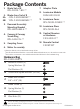
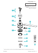
Package Contents 1. Blade Set of 8 RPL-F2001-*-BD-** 2. Blade Arms Set of 8 2A. RPL-F-2001-BARM-** 2B. RPL-F-2001-BARM2-** 7. Adapter Plate 8. Luminaire Module F4IN-120V-R1-30 1 2 9. Luminiare Cover RPL-F2001-COVER-** 3. Downrod Assembly Mounting Bracket RPL-HGR-ASM-6-** 10. Luminiare Glass RPL-F2001-GLA 4. Canopy & Canopy Screw Ring RPL-CAN-CYL-** 11. Control Receiver w/Hardware F-R3-2001-0** 5. Coupling Cover 12. Remote Control F-RCBT-WT 6.
Hanging Weight: 35 lbs MAC ID IMPORTANT: Please make note of the MAC ID on the receiver and keep it in a safe place.
1. Mounting Options CAUTION: To prevent electrical shock, ensure electricity has been turned off at the circuit breaker before beginning. If there isn’t an existing UL/cUL listed outlet box, please refer to the following instructions. Secure the outlet box directly to the building structure. Use appropriate fasteners and building materials. The outlet box and support structure must be able to fully support the moving weight of the fan (at least 35 lbs/15.9 kg). Do not use plastic outlet boxes.
1 1. 3 Support Brace 2. Outer Box 1 3. Joist 2 1A 1. Outer Box 1 1B Support Ceiling Max 30° Angle 1 1. 2 3 Support Brace 2. Mounting Bracket 3. Recess Outlet Box 1C 1.
2. Installing the Mounting Bracket Remember to disconnect the power at the circuit breaker. 1. Remove 1 of 2 screws from the bottom of the mounting bracket and save for use in section 11. Loosen the other screw (Fig. 2). 2. Pass the 120-volt supply wires through the center hole in the mounting bracket as shown (Fig. 2A). 3. Secure the mounting bracket to the ceiling outlet box with the screws and washers provided with your outlet box. Use Part A if needed 4.
2 2A To Switch B A 1 1 (HOT) (Neutral) To Switch (No Neutral) (HOT)/ Switch 1. 2 3 A 2 1. Mounting Bracket 2. Screw (Ground) *Bare or Green (Ground) *Bare or Green cUL Listed Electrical Box 2. Mounting Screws (outlet box screws not included) 3 3.
4. Hanging the Fan 1. Remove screw from hanger ball. Remove hanger ball and cross pin. 2. Loosen 2 screws, clevis pin and cotter pin (Fig. 4A). 3. Install coupling cover, canopy screw ring, canopy and downrod assembly into motor housing as shown (Fig. 4). 4. Align downrod and motor collar holes, re-insert pins and screws (Fig. 4B). 5. Slip up canopy and canopy screw cover. Re-install hanger ball with cross pin in correct place (Fig. 4). 6. Seat all into the mounting bracket.
4 4A 4B FR- W 2 0 0 1 Renegade Instructions 15
5. Making the Electrical Connections WARNING: Installation of this fan requires that a three-conductor cable (including ground wire) which should run between ceiling and wall outlet box. WARNING: Check to see that all connections are tight, including ground, and that no bare wire is visible at the wire nuts, except for the ground wire. Insert the receiver into the mounting bracket with the flat side of the receiver facing the ceiling (Fig. 5). Motor to Receiver & Receiver to housing supply wires (Fig. 5A).
5 1. Mounting Bracket 2.
6. Installing the Wall Control (Optional) NOTE: Wall Control not included. A bluetooth wall control accessory can be purchased separately. 1. Connect the green wire marked “GROUND” from the wall control to the copper wire from the wall outlet box that feeds back to the circuit breaker – important for proper fan function (Fig. 6). 2. Connect the black wire marked “LINE IN” from the wall control to the black LINE VOLTAGE wire from the wall outlet box that feeds back to the circuit breaker (Fig. 6). 3.
6A 1 2 3 1. Wall Outlet 2. Wall Control 3. Wall Mounting Plate 4. Mounting Plate Screws 5. Wall Plate 4 5 Multi-location wiring Individually pair each of the wall controls with the fan receiver using the pairing instruction. See page 25.
7. Finishing the Installation 1. Secure wire connectors with supplied wire ties. 2. Install canopy to mounting bracket with the screw removed in section 4 (Fig. 7). 3. Install canopy screw ring as shown (Fig. 7). 8. Installing the Luminaire Module Installation of the Luminaire (Glass/Cover) is optional. NOTE: Skip to step 6 if you are not installing the (Glass Shade/LED module). 1. Remove 1 of 3 screws and loosen the others (DO NOT REMOVE) from the motor assembly (Fig. 8). 2.
7 8A FR- W 2 0 0 1 8 8B Renegade Instructions 21
9. Controlling the Fan Your fan was delivered to you with the included control paired to your fan. A: Light On/Off, Bright/Dim B: Fan On/Off, Speed Up/Down C: Season (Summer/Winter) Air-Gap Switch: Pull tab to power off in case of emergency. Not necessary for normal fan operation (only included with wall control). NOTE: Your fan features 6 speeds. An audible tone will indicate when the speed is increased or decreased. When the fan has reached the minimum/maximum speed level the fan will beep twice.
9 9A A B C Air-Gap Switch* Wall Control * Air-Gap Switch only included with wall control Remote Control Summer Mode Winter Mode (Counter-Clockwise) (Clockwise) 9B Fan On/Off Light On/Off Fan Direction Press and hold button for 4 seconds. Press and hold button for 4 seconds. Press and hold button for 4 seconds. Fan On/Off: Press and hold button for 4 seconds. The LED on the remote will flash green and all connected fans will beep to indicate the message has been received.
10. Factory Reset If advised by fan support, you can reset your fan to factory settings by referring to either (Fig. 10, 10A or 10B). NOTE: Changes to your Wi-Fi network settings (SSID or Security Passphrase) will prevent your fan from connecting to the cloud. You can re-establish connectivity by performing a Wi-Fi Reset and using the Modern Forms app to reconfigure the fan to connect to the network with the new settings. 11. Breeze Mode 1.
9C 10 Pairing Unpairing Fan Wi-Fi Reset Press and hold buttons for 10-15 seconds. To purge, press and hold buttons for 4 seconds.
13.
Sloped Ceiling Kit Designed to accommodate buildings with steeper sloped ceilings up to 45° or 12/12 pitch (Downrod Only) XF-SCK Coupler Connects two downrods (Downrod Only) XF-I Downrod XF-12 - 12” Downrod | XF-18 - 18” Downrod XF-24 - 24” Downrod | XF-36 - 36” Downrod XF-48 - 48” Downrod | XF-60 - 60” Downrod XF-72 - 72” Downrod FR- W 2 0 0 1 Renegade Instructions 27
14. Troubleshooting My Fan Will Not Start CAUTION: Make sure the main power is turned off! 1. Check main and branch circuit fuses or circuit breakers. 2. Check line wire connections to fan and switch wire connections in the switch housings. My Fan Is Noisy 1. Allow for 24-hour break-in period. Most noises associated with a new fan will go away during this time period. 2. Check to make sure the screws which attached to the blades (and blade arms when applicable) are tight. 3.
My Fan Is Not Producing Enough Air Movement If possible, please consider using a longer than included downrod. My Remote Or Wall Control Is Not Controlling My Fan Verify that the fan is receiving power by power cycling the fan. To Do This: 1. Cut power to the fan via standard On/Off wall switch, or the breaker if standard wall switch is not applicable. 2. Wait at least 10 seconds, and then restore power. 3. The fan will power on in Pairing mode for 3 minutes. 4. Press and hold ( for 10-15 seconds.
14. Troubleshooting My Fan Failed to Join The WiFi Network 1. Make sure you entered the correct Wi-Fi password and your mobile device is connected to the same network you attempted to connect the fan. 2. Make sure you are within the router manufacturer’s specified range. If all of these steps have failed - please power cycle your fan and router and retry. What Is Power Cycling and How Do I Power Cycle My Fan? Power cycling is the act of temporaily removing the power source for your fan.
What Is Pairing? Pairing is the process of connecting your Modern Forms remote or wall control to your fan. Your fan comes pre-paired to your included remote control. However, if you want additional controls for your fan or if you’re replacing a control, refer to the pairing and unpairing section of the instructions. What Is a Factory Reset? Factory Reset is a restore of the fans original settings.
Certificate of Warranty Congratulations on your new purchase. Your new Modern Forms Smart Fan is engineered to make life easier every day. Modern Forms creates future-forward fans and luminaires that provide energy savings and outstanding efficiency. Our dedication to doing things the right way goes beyond our love for amazing products.
parte del distribuidor y, en consecuencia, cualquier daño consecuencial o costo de mano de obra que surja de un defecto se excluye expresamente. Esta garantía no se aplicará a los productos que hayan sido alterados, instalados incorrectamente, mal manejados o mal utilizados. La notificación de un defecto por escrito debe ser recibida por Modern Forms dentro de los cinco (5) años a partir de la fecha de compra (o según el período de tiempo indicado en el material).
Renegade Instructions FR-W2001
FR- W 2 0 0 1 Renegade Instructions 35
FR-W 2001 modernforms.