
Installation & Assembly

Modernforms.com
Phone (866) 810.6615
Fax (800) 526.2585
Headquarters/Eastern Distribution Center
44 Harbor Park Drive
Port Washington, NY 11050
Central Distribution Center
1600 Distribution Ct
Lithia Springs, GA 30122
Western Distribution Center
1750 Archibald Ave
Ontario, CA 91761
Modern Forms retains the right to modify the design of our products at any time as part of the company's continuous improvement program. Oct. 2019 2
INSTALLATION INSTRUCTION
508-Indoor Wall Sconce
WS-50820/WS-50827
Fig.1
PREPARATION
1. Shut off the power at the circuit
breaker and remove existing fixture,
including the crossbar.
2. Carefully unpack your new fixture
and lay out all the parts on a clear
area. Be careful not to lose any
small parts necessary for
installation.
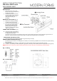
MOUNTING THE FIXTURE (Fig. 1)
3. Remove the mounting screw (B)
and back plate from the fixture.
4. Secure the mounting back plate to
the junction box using standard
junction box screws that comes
with the junction box. Note: the
side of the mounting plate marked
“GND” must face out.
CONNECTING THE WIRES (Fig. 2)
5.
Connect the driver’s input wires to
junction box wires as shown in Fig.
2, making sure that all wire
connectors (A) are secured. If your outlet box has a green or bare copper ground wire, connect the fixture’s ground wire to it.
Otherwise, connect the fixture’s ground wire directly to the back plate using the green screw provided.
COMPLETING THE INSTALLATION
6. Secure the fixture to the mounting back plate using the mounting screw (B) .
DIMMING WIRING INFORMATION (Fig. 3)
7. This fixture features electronic low voltage (ELV or TRAIC) or 0-10V dimming capabilities. See notes below for specific dimming
wires information.
8. To utilize ELV or TRAIC dimming: use wires black (hot), white (neutral) and bare copper ground wire (ground).
9. To utilize 0-10V dimming: use wire purple (dim+), gray (dim-), black (hot), white (neutral) and bare copper ground wire (ground).
NOTE: Make sure to connect 0-10V prior to power-up the fixture in order to allow the 0-10V dimming to function properly.
Fig. 2 Wiring
Fig. 3 Driver Wires