
Installation & Assembly

Modern Forms
www.modernforms.com
Phone (800) 526.2588 • Fax (800) 526.2585
Headquarters/Eastern Distribution Center
44 Harbor Park Drive • Port Washington, NY 11050
Phone (516) 515.5000 • Fax (516) 515.5050
Western Distribution Center
1750 Archibald Ave • Ontario, CA 91761
Phone (800) 526.2588 • Fax (800) 526.2585
Modern Forms retains the right to modify the design of our products at any time as part of the company's continuous improvement program.
3
PREPARATION
1. Shut o the power at the circuit breaker and remove existing xture, including the crossbar.
2. Carefully unpack your new xture and lay out all the parts on a clear area. Be careful not to lose any small parts necessary for installation.
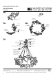
MOUNTING THE FIXTURE Fig. 1
3. Remove the mounting screw (C) from the xture.
4. Drill holes in the wall aligned with the key holes located in the mounting back plate, insert the plastic anchor (D).
5. Secure back plate to the junction box using junction box screws (B), fasten it to the wall using wood screw (E).The side of the mounting
plate marked “GND” must face out.
6. Connect the two lamp body components with hexagon nuts (F) and nuts (I) (Fig. 3).
7. Then, in turn the third, the fourth Lamp body assembly, after installed, like a circle (Fig. 4).
8. Steel cable through the Lamp canopy cable-gripper. Then braided wire line buckle through the gasket (G) and (H) hexagonal nut fastening
at the Lamp canopy.
9. Braided wire can be divided into two groups, the total of two groups, one group connection one drive with wire connectors (A), another
group connection another drive with wire connectors (A).
10. Adjust the xture wire length by pushing the cable gripper on the canopy and pulling the wire as desired. Make sure the wires are the same
length.
a. Retract these wires close to a desirable length to within the canopy before securing the xture in place. Using the cable gripper to
adjust more than 18” of wire length is not desirable.
b. Warning: Shortening these cables without professional help or electronic background is not advisable. Any modications to the xture
will result in voiding the warranty of the product.
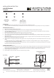
CONNECTING THE WIRES Fig. 2
11. Connect the driver input wires with junction box wires as shown in Fig.2, making sure that all wire connectors (A) are secured. If your outlet
box has a green or bare copper ground wire, connect the xture’s ground wire to it. Otherwise, connect the xture’s ground wire directly to
the mounting plate using the green screw provided. After wires are connected, tuck them carefully inside the junction box.
12. Hook the safety cords to the back plate.
13. Place the xture over the back plate and secure it with mounting screws (C).
Back Plate Dimensions
7MBC252008
INSTALLATION INSTRUCTION
648-LED Pendant
PD-64861
G0
HARDWARE (CONTINUED)
G
Hexagon Nuts
Qty: 4 pcs + 1 Extra
7MPM0904C1
1/8-27x1/8
H
Gasket
Qty: 4 pcs + 1 Extra
7MPH1610A1
I
Nut
Qty: 8pcs + 1 Extra
4MBA161208BA (AL)
4MBA161208BK (BK)
4MBA161208BB2 (AB)
Fixture Wires
Black or
Smooth
Fixture Wires
White or
Ribbed
Fixture Wires
Bare wire
(Ground)
House Wires
Black
(Hot)
House Wires
White
(Neutral)
House Wires
Green or Bare Copper
(Ground)
Fig. 2 Wiring
1 ⁄”
3 ⁄”
9 ½”
1 ¾”