
Installation Sheet


2
INSTALLATION INSTRUCTIONS
PD-W24216
Phone (800) 526.2588
Fax (800) 526.2585
44 Harbor Park Drive
Port Washington, NY 11050
1600 Distribution Ct
Lithia Springs, GA 30122
1750 Archibald Avenue
Ontario, CA 91760
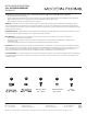
Black or
Smooth
White or
Ribbed
Bare wire
(Ground)
Black
(Hot)
White
(Neutral)
Green or Bare Copper
(Ground)
1. Shut o the power at the circuit breaker and remove existing
xture, including the crossbar.
2. Carefully unpack your new xture and lay out all the parts on
a clear area. Be careful not to lose any small parts necessary
for installation.
3. Remove the mounting screw (C) and the silicone gasket (D) from
the canopy.
4. Secure the mounting plate to the junction box using junction box screws.
Note:(i) using any other non-original-manufacturer provided junction
box screw may result in safety issue;
(ii) The side of the mounting plate marked “GND” must face out.
5. Remove the screw (E) and bottom cover from the xture.
6. Insert four clear seedy glass along the inner wall of the xture,
then secure the bottom cover to the xture using the screw (E).
7. Choose the number of rods suitable for your application. Thread
wire from xture through stems, swivel, and canopy. Tighten so
they are attached securely.
8. Connect the driver output wire with xture wire as shown in (Fig. 3 )
red to the red, and black to the black. make sure connectors (B) are secured.
9. Connect the driver input wires to junction box wires as shown (Fig. 2).
Make sure that all wire connectors (A) are secure. If your outlet box
has a green or bare copper ground wire, connect the xture’s ground
wire to it. Otherwise, connect the xture’s ground wire directly to the
back plate using the screw provided. After wires are connected, tuck them
carefully inside the junction box.
10 Secure the xture by mounting the canopy to the mounting back plate.
Slide the canopy in the direction of the notch until it latches in place.
Fasten the canopy to the mounting back plate using the mounting screw(C).
and the silicone gasket (D).
11. For slope ceiling application, rotate swivel at the top of the stem to ensure
luminaire is aiming down (Fig. 4).
Clear Glass
Share With:WS-W24218
(RPL-GLA-24218)
Screw
Bottom cover
1X6" Rod
RPL-ROD-OUT06-BK
Junction Box
Wire
Connector
Wire
Connector
Canopy
Swivel
Mounting Plate
Junction Box Screw
E
Driver
Ground Wire
Mounting
Screw
Silicone
Gasket
3X12" rod
RPL-ROD-OUT12-BK
Acrylic Diffuser
(RPL-DIF-24218)
Turn to down
White - Neutral
Black - Hot
Red +
Black -
Red +
Black -
Driver
Input
Output
Canopy