
Installation Sheet

3Modern Forms retains the right to modify the design of our products at any time as part of the company's continuous improvement program.
modernforms.com
Phone (800) 526.2588
Fax (800) 526.2585
Headquarters/Eastern Distribution Center
44 Harbor Park Drive
Port Washington, NY 11050
Central Distribution Center
1600 Distribution Ct
Lithia Springs, GA 30122
Western Distribution Center
1750 Archibald Avenue
Ontario, CA 91760
PREPARATION
1. Shut o the power at the circuit breaker and remove existing xture, including the crossbar.
2. Carefully unpack your new xture and lay out all the parts on a clear area. Be careful not to lose any small parts necessary for installation.
INSTALLATION
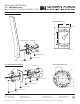
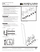
MOUNT ON SWITCH BOX (Fig. 1)
3. Remove the mounting screw (C1) from the xture.
4. Connect the xture input wire to switch wires as shown in Fig. 3, making sure that all wire connectors (A1) are secured. If your outlet box
has a green or bare cooper ground wire, connect the xture’s ground wire to it. Otherwise, connect the xture’s ground wire directly to the
back plate using the green screw provided. After wires are connected, tuck them carefully inside the switch box.
5. Secure the mounting plate to the switch box using the junction box screw (B1). The side of the mounting plate marked “GND” must face out.
6. Place the xture over the mounting plate, and secure it with mounting screw (C1).
OR
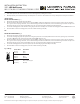
MOUNT ON JUNCTION BOX (Fig. 2)
3. Remove the mounting screw (C1) from the xture.
4. Secure the mounting ring (E1) to the junction box using the junction box screw (B1). Make sure the two holes (Spacing 2¾”) are horizontal
as shown in Fig. 2. The side of the mounting plate marked “GND” must face out.
5. Connect the xture input wire to switch wires as shown in Fig. 3, making sure that all wire connectors (A1) are secured. If your outlet box
has a green or bare cooper ground wire, connect the xture’s ground wire to it. Otherwise, connect the xture’s ground wire directly to the
back plate using the green screw provided. After wires are connected, tuck them carefully inside the switch box.
6. Secure the mounting plate and conversion plate (F1) to the mounting ring with assembly screw (D1)
7. Place the xture over the mounting plate, and secure it with mounting screw (B1).
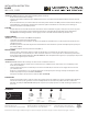
Fixture Wires
Black or
Smooth
Fixture Wires
White or
Ribbed
Fixture Wires
Bare wire
(Ground)
House Wires
Black
(Hot)
House Wires
White
(Neutral)
House Wires
Green or Bare Copper
(Ground)
Fig. 3 Wiring
INSTALLATION INSTRUCTION
117 - LED Wall Sconce
WS-11718/WS-11718F/WS-11722/WS-11722F