
Installation Sheet

2
INSTALLATION INSTRUCTIONS
179-Outdoor Wall Sconce
WS-W17909/WS-W17912/WS-W17917
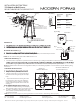
Fixture Wires
Black or
Smooth
Fixture Wires
White or
Ribbed
Fixture Wires
Bare wire
(Ground)
House Wires
Black
(Hot)
House Wires
White
(Neutral)
House Wires
Green or Bare Copper
(Ground)
FIG. 2 WiringFIG. 1
modernforms.com
Phone (800) 526.2588
Fax (800) 526.2585
Headquarters/Eastern Distribution Center
44 Harbor Park Drive
Port Washington, NY 11050
Central Distribution Center
1600 Distribution Ct
Lithia Springs, GA 30122
Western Distribution Center
1750 Archibald Avenue
Ontario, CA 91760
Modern Forms retains the right to modify the design of our products at any time as part of the company's continuous improvement program. Jan 2019
ANUARY, 2017
modernforms.com
Phone (800) 526.2588
Fax (800) 526.2585
Headquarters/Eastern Distribution Center
44 Harbor Park Drive
Port Washington, NY 11050
Central Distribution Center
1600 Distribution Ct
Lithia Springs, GA 30122
Western Distribution Center
1750 Archibald Avenue
Ontario, CA 91760
WS-W17917
Back Plate Dimensions
1
3
8
″
5
3
4
″
4
1
8
″
4
1
8
″
4
1
2
″
WS-W17909 & WS-W17912
Back Plate Dimensions
1
3
8
″
1
3
4
″
1
3
4
″
PREPARATION
lose any small parts necessary for installation.
MOUNTING THE FIXTURE (Fig. 1)
4.
Secure the mounting back plate to the junction box using the screws provided with the junction box.
CONNECTING THE WIRES (Fig. 2)
5. Connect the driver’s input wires to junction box wires as shown in Fig. 2, making sure that all wire connectors (A) are secure. If your outlet
the back plate using the green screw provided. After wires are connected, tuck them carefully inside the junction box.
COMPLETING THE INSTALLATION
using the mounting screw (B) .
8. Twist the reeded glass (C) into the lamp body,
and then twist the clear glass (D) into the lamp
body.
9. To prevent moisture from entering the outlet
box and causing a short, use clear caulking (ie:
indoor/outdoor silicone sealant) to outline the
outside of fixture backplate where it meets the
wall (Fig. 3).
NOTE: DIMMING WIRING INSTRUCTIONS (Fig. 4)
10. To utilize ELV or TRAIC dimming: use black (hot),
white (neutral) and bare copper ground wires (ground).
11. To utilize 0-10V dimming: use purple (dim+), gray
(dim-), black (hot), white (neutral) and bare copper
ground wires (ground).
Fig. 3 Sealing
Junction Box
Caulking
White - Neutral
Black - Hot
Purple - Dim+
Gray - Dim-
Red - Fixture+
Black - Fixture-
Fig. 4
Wire Connector
Mounting Screw
Lamp Body
Junction Box
Ground Wire
A
B
Reeded Glass
(WS-W17917:RPL-GLA-17917-01
WS-W17912:RPL-GLA-17912-01
WS-W17909:RPL-GLA-17909-01)
CLEAR GLASS
(WS-W17917:RPL-GLA-17917-02
WS-W17912:RPL-GLA-17912-02
WS-W17909:RPL-GLA-17909-02)
Driver
C
Si
l
i
co
n
e
G
a
s
k
et
NOTE: The side of the mounting plate marked "GND" must face out.
NOTE: This fixture features electronic low voltage (ELV or TRAIC) or 0-10V dimming capabilities. See notes below for specific dimming wiring
instructions.
NOTE: Make sure to connect 0-10V prior to powering up the fixture in order to allow the 0-10V dimming to function properly.