Modern Robotics Inc. Sensor Documentation Version 1.4.
Sensor Documentation Modern Robotics, Inc. Contents 1. 2. 3. 4. 5. Document Control ................................................................................................................. 3 Introduction ........................................................................................................................... 4 Three-Wire Analog & Digital Sensors .................................................................................. 5 3.1. Program Control Button (45-2002) .........
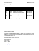
Sensor Documentation Modern Robotics, Inc. 1. Document Control Revision History Version Date 1.0.0 6/29/16 1.0.1 9/9/16 1.2.0 12/6/16 1.3.0 2/6/17 1.3.1 2/8/17 1.4.0 4/12/17 1.4.1 1.4.
Sensor Documentation Modern Robotics, Inc. 2. Introduction The following document is a guide for the use and implementation of all Modern Robotics Sensors. Modern Robotics Sensors are built in a robust plastic housing with either a three or four wire connector for easy connection to various Modern Robotics Controllers. These sensors are designed for work, play and education with a housing tailored to fit the Matrix Robotics System’s 8mm grid.
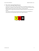
Sensor Documentation Modern Robotics, Inc. 3. Three-Wire Analog & Digital Sensors All three-wire sensors connect to either a digital port or an analog port. Therefore, if it is a digital sensor, it produces a value of either 0 or 1. If the sensor is analog, it produces a value between 0 and 255. The sensors consist of a black, red and yellow wire. The black wire is the ground wire and must line up with the black bar on the right side of the port.
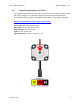
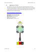
Sensor Documentation 3.1. Modern Robotics, Inc. Program Control Button (45-2002) The Program Control Button (PCB) is used to provide the user the ability to interact with the running program. It can be used to stop and start programs without having to intercept the power. This sensor is designed to work with the Core Spartan Controller. http://modernroboticsinc.
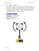
Sensor Documentation 3.2. Modern Robotics, Inc. Rate Gyro (45-2004) The Rate Gyro is used to detect the rate of rotation. When the Rate Gyro is completely still, the returned reading is 1.4V which produces a reading of 280° ±2°. With the sensor idle at 280°, a Counter Clockwise (CCW) rotation will increase the value of the reading and then return to 280° once movement is stopped.
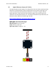
Sensor Documentation 3.3. Modern Robotics, Inc. Optical Distance Sensor (45-2006) The Optical Distance Sensor (ODS) is an analog sensor that uses electro optical proximity detection to calculate distance from an object based on the intensity of the light. This sensor can accurately calculate distances between 1 cm and 15 cm. Lighter colored objects will return a more accurate and consistent reading. Try a variety colors and materials to see what works best for you.
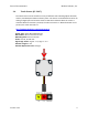
Sensor Documentation 3.4. Modern Robotics, Inc. Touch Sensor (45-2007) The Touch Sensor can be used for an array of different tasks including object detection, counter, standard push button and many more. The sensor can be attached to either an analog or digital port and contains a built-in LED which indicates when the sensor is activated. When the button is pressed, the value returned is 1. When the button is not pressed, the value returned is 0. http://modernroboticsinc.
Sensor Documentation 3.5. Modern Robotics, Inc. Light Sensor (45-2015) The Light Sensor detects the ambient light level using a phototransistor. The value returned is a quasi-logarithmic analog value that allows the Light Sensor to be used over at least four decades of light. This means that the Light Sensor can detect slight changes in light and dark environments. A value of 0 indicated no light and a value of 255 indicated the sensor is flooded with light. http://modernroboticsinc.
Sensor Documentation 3.6. Modern Robotics, Inc. Magnet Sensor (45-2020) The Magnet Sensor detects a magnetic field and returns the strength based on the distance away from the sensor. When the returned value is increasing, the sensor is detecting the north pole of the magnet. If the value returned is decreasing, then the sensor is detecting the south pole magnet. The sensor value ranges from ≈0 to ≈700 where 340 indicates no magnetic field. http://modernroboticsinc.
Sensor Documentation Modern Robotics, Inc. 4. Four-Wire Digital I2C Sensors All four-wire sensors are I2C sensors. I2C stands for Inter-Integrated Circuit and is used for communication between two or more devices. All Modern Robotics I2C sensors have four wires: Black, Red, Yellow and White. The black wire is the ground wire and must line up with the black bar on the right side of the port. The red wire is the power wire that connects to 5V for all the sensors to operate on.
Sensor Documentation Modern Robotics, Inc. Standard I2C Memory Map for 4 Wire Sensors Register 0x00 0x01 0x02 0x03 0x04-0x6F 0x70-0xFF Function Sensor Firmware Revision Manufacturer Code Sensor ID Code Command Register (optional) Data Registers Unavailable Sensor Codes Location 0x00 will contain the major and minor firmware revision numbers as two hex nibbles. Location 0x01, the manufacturer code byte, will contain 0x4D (“M”). Location 0x02, the sensor ID code, will contain an ID code as defined above.
Sensor Documentation 4.1. Modern Robotics, Inc. Compass (45-2003) The Compass uses a magnetometer and an accelerometer to calculate heading data based on Earth’s magnetic field. The compass can return the heading data, accelerometer data and magnetometer data to the user. Anything that generates a magnetic field must be moved away from the sensor like power cables, motor or magnetic material.
Sensor Documentation Register Function 0x00 0x01 0x02 0x03 0x04/0x05 0x06/0x07 0x08/0x09 0x0A/0x0B 0x0C/0x0D 0x0E/0x0F 0x10/0x11 0x12/0x13 0x14/0x15 0x16/0x17 0x18/0x19 0x1A/0x1B 0x1C/0x1D 0x1E/0x1F 0x20/0x21 0x22/0x23 0x24/0x25 Command 0x00 0x43 0x58 0x59 0x5A 0x47 0x55 0x44 0x57 Version 1.4.3 Modern Robotics, Inc.
Sensor Documentation Modern Robotics, Inc. During normal operation, the LED will blink briefly at 1Hz. During Hard Iron Calibration, the LED will blink at ½Hz. During tilt up and tilt down calibration the LED will be on during a period of calibration measurement. Hard Iron Calibration: Hard Iron Calibration is entered by setting the command location to 0x43. Once Hard Iron Calibration is active rotate the Compass 360°, making sure it does not tilt, for a period of 5 seconds.
Sensor Documentation Modern Robotics, Inc. Accelerometer Scale Coefficient: The Accelerometer Scale Coefficient is adjusted to be approximately 1mg/count. If greater measurement accuracy is required, the Accelerometer Scale Coefficient (fsb/lsb) may be set by the user. This can be simply done by setting the device perfectly vertical and obtaining the accelerometer X value via registers 0x06 and 0x07.
Sensor Documentation 4.2. Modern Robotics, Inc. Integrating Gyro (45-2005) The Integrating Gyro uses a 3-axis chip to obtain X, Y and Z coordinates as well as an integration of the Z-axis to provide heading data. The integrated Z value is an integration of the Z-axis over time and this value is used for both internal calculations and to provide an Absolute heading (-∞ - ∞) as opposed to the Cartesian heading (0° – 359°). http://modernroboticsinc.
Sensor Documentation Register Function 0x00 0x01 0x02 0x03 0x04/0x05 0x06/0x07 0x08/0x09 0x0A/0x0B 0x0C/0x0D 0x0E/0x0F 0x10/0x11 Command 0x00 0x4E 0x52 Modern Robotics, Inc.
Sensor Documentation Modern Robotics, Inc. Integrated Z Value: The integrated gyro Z value returns the current value obtained by integrating the Z axis rate value, adjusted by the Z axis offset continuously. This integrated value can be reset to 0 by issuing command 0x52. This value can also be used as a signed heading value where CCW is in the positive direction and CW is in the negative direction.
Sensor Documentation Modern Robotics, Inc. Step 3: Calculate Register Values Register Value (lsb:fsb) = 1.01 * 256 = 258.56 Round Down: 258 = 0x0102 Step 4: Enter Values into Z Axis Scaling Coefficient Register Z Axis Scaling Coefficient = 0x10 (fsb)/0x11 (lsb) Register 0x10 (fsb) = 0x02 Register 0x11 (lsb) = 0x01 Click “WRITE” to enter the values into the registers. You can then “READ” back to verify the registers contain the correct value.
Sensor Documentation 4.3. Modern Robotics, Inc. Range Sensor (45-2008) The Range Sensor combines ultrasonic and optical measuring elements to obtain a reading between 1cm and 255cm. The ultrasonic accurately measures distance to a target up to 255cm away, but it losses accuracy if the object is closer than 5cm. This is where the optical sensor comes into play as it can measure from 1cm out to about 7cm. The target shape and surface material will influence to detectable range. http://modernroboticsinc.
Sensor Documentation Register 0x00 0x01 0x02 0x03 0x04 0x05 Modern Robotics, Inc. Function Sensor Firmware Revision Manufacturer Code Sensor ID Code Not Used Ultrasonic reading (cm) Optical reading Ultrasonic: The ultrasonic element works by one of the transducers emitting a sound wave and the other receiving the sound wave. This reading is accurate between 5cm and approximately 255cm. Since the value returned is in units of centimeters, the return is linear.
Sensor Documentation 4.4. Modern Robotics, Inc. IR Locator 360 (45-2009) The IR Locator 360 is a 360° infrared detecting sensor. There are 4 IR photo diodes that are arranged to provide an accurate reading of the IR source. The sensor provides 600Hz and 1200Hz readings that produce results at a resolution of 5°. http://modernroboticsinc.
Sensor Documentation Register 0x00 0x01 0x02 0x03 0x04 0x05 0x06 0x07 Modern Robotics, Inc. Function Sensor Firmware Revision Manufacturer Code Sensor ID Code Not Used 1200 Hz Heading in 5° increments 1200 Hz Signal Strength 600 Hz Heading in 5° increments 600 Hz Signal Strength The frequencies are channels that the IR Locator 360 uses to tell the difference between IR emitting sources. Both 600Hz and 1200Hz IR signals may be present at the same time which results in two identifiable IR sources.
Sensor Documentation 4.5. Modern Robotics, Inc. Sound Generator (45-2016) The Sound Generator can generate a sound based on volume, pitch and duration. This sensor also can overwrite settings during a tone to change how it sounds, change the volume, or to extend the duration of the tone. http://modernroboticsinc.com/sound-generator Sensor Type: Four Wire I2C Sensor Default I2C Address: 0x34 Sensor ID Code: 0x53 Dimensions: 32 mm x 32 mm x 19 mm Mounting Holes: 24 mm x 24 mm Power: 5 V DC, 20 mA max.
Sensor Documentation Register 0x00 0x01 0x02 0x03 0x04 0x05/0x06 0x07 Modern Robotics, Inc. Function Sensor Firmware Revision Manufacturer Code Sensor ID Code Not Used Sound Level Pitch (lsb/msb) Duration The order if the 4 control bytes, Sound Level, Pitch low, Pitch high and Duration are arranged such that a signal 4 byte write can be used to initiate a tone. Sound Level: Controls the amplitude of the output signal from 0 to 3 where 0 is the quietest and 3 is the loudest.
Sensor Documentation 4.6. Modern Robotics, Inc. IR Seeker V3 (45-2017) The IR Seeker V3 consists of two IR detectors used to locate an IR source and calculate it’s heading relative to the front of the sensor. The sensor can read incoming infrared light at 600Hz and 1200Hz. The sensor has a range of 2.75m with 150° field of view. It is primarily intended to provide head-on resolution when locating an IR source. http://modernroboticsinc.
Sensor Documentation Register 0x00 0x01 0x02 0x03 0x04 0x05 0x06 0x07 0x08/0x09 0x0A/0x0B 0x0C/0x0D 0x0E/0x0F Modern Robotics, Inc.
Sensor Documentation 4.7. Modern Robotics, Inc. Color Sensor (45-2018) The Color Sensor is used to read the color of an object and returns a handful of useful data using a red/green/blue reading. This data includes a color number that corresponds to the color line in the documentation, as well as raw and adjusted readings. The material of the surface being read and the ambient light in the room will affect the results. Therefore, the Color Sensor should be recalibrated for different environments.
Sensor Documentation Modern Robotics, Inc. Register 0x00 0x01 0x02 0x03 0x04 0x05 0x06 0x07 0x08 0x09 0x0A 0x0B 0x0C 0x0D 0x0E/0x0F 0x10/0x11 0x12/0x13 0x14/0x15 0x16/0x17 0x18/0x19 0x1A/0x1B 0x1C/0x1D Command 0x00 0x01 0x35 0x36 0x42 0x43 Version 1.4.
Sensor Documentation Modern Robotics, Inc. Commands: The command register may be set to any of the values from the command table. Once a command value is entered into the command register the value will be saved in the EEPROM. Active Measurement Mode Command = 0x00 In active measurement mode, the sensor takes a reading by illuminating a surface with a white LED and measuring the reflected light. Active mode is useful in identifying the color of a surface.
Sensor Documentation Modern Robotics, Inc. Color Number: The color number register returns a single number representing the color estimate. The number corresponds to the following figure. 0 1 2 3 4 5 6 7 8 9 10 11 12 16 13 14 15 Color Values: The color values are returned separately as red, green, blue and white. The color value is a measure of the current detection levels for each primary color. Color Index Number: The color index number is a single 6 bit number.
Sensor Documentation 4.8. Modern Robotics, Inc. Color Beacon (45-2019) The Color Beacon is used to display one of seven colors or any set custom color based on RGB values. The beacon can also indicate RED/BLUE team colors with the use of a magnet. Simply hold a magnet over the Hall Effect sensor on the left side of the beacon to change between RED, BLUE and normal operating mode. There is no code or setup needed to operate as a team indicator. http://modernroboticsinc.
Sensor Documentation Register 0x00 0x01 0x02 0x03 0x04 0x05 0x06 0x07 Color Value N/A 0 1 2 3 4 5 6 7 8 Modern Robotics, Inc. Function Sensor Firmware Revision Manufacturer Code Sensor ID Code Not Used Color Number Red Strength Green Strength Blue Strength Function Hall Effect changes LED ( RED/BLUE/OFF) LEDs OFF Red Green Yellow Blue Purple Teal White Custom Color Color Number: The color number represents the color the Color Beacon will display.
Sensor Documentation Modern Robotics, Inc. 5. Controllers Modern Robotics sensors are designed to be used on multiple control devices like the Core Spartan Controller or Core Device Interface Module. The sensors may also be used on any Arduino board, Raspberry Pi, BeagleBone as well as most other types of microcontrollers or embedded systems. Version 1.4.
Sensor Documentation 5.1. Modern Robotics, Inc. Core Spartan Controller (45-2000) The Core Spartan Controller makes it easy to connect, control, and program your robot with the use of the Arduino IDE. The Core Spartan Controller is designed to control sensors, servos and motors. The Core Spartan Library must be installed on your computer to have access to all the available functions that are used in controlling the Core Spartan Controller and its sensors.
Sensor Documentation 5.2. Modern Robotics, Inc. Core Device Interface Module (45-2001) The Core Device Interface Module (CDI) connects external sensors and other devices to an Android device or PC. With a total of 26 ports are divided into five general classes: Digital Input/Output, Analog Input, Analog Output, PWM and I2C. The CDI gives a convenient way to attach a wide range of Modern Robotics sensors or home brewed devices to control your world.