
Service manual


GGeenneerraall IInnssttrruuccttiioonnss FFoorr DDoouubbllee WWaallll ((TTyyppee BB)) VVeenntt PPiippee
IInnssttaallllaattiioonn::
A single section of double wall vent pipe used with a positive
pressure vent system (cat III or IV as listed in table 4.1) must
follow installation requirements for single wall vent pipe. Under no
circumstances should two or more sections of double wall vent
pipe be joined together within one positive pressure vent system
due to the inability to verify a complete seal of the inner pipes.
Multiple sections of double wall vent pipe may be used with a
negative pressure vent system (cat I or II as listed in table 4.1).
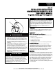
1. How to attach a single wall vent cap to double wall (type B)
vent pipe:
A. Look for the “flow” arrow on the vent pipe. Attach the vent
cap to the exhaust end of the double wall vent pipe.
B. Slide the vent cap inside the pipe.
C. Drill a hole through the pipe and the vent cap. Using 3/4”
long sheet metal screws, attach the cap to the pipe.
2. How to connect a single wall vent system to a double wall
(type B) vent pipe:
A. Slide the single wall pipe inside the inner wall of the
double wall pipe.
B. Drill a hole through both walls of the double wall pipe and
through the single wall pipe. Using 3/4” sheet metal
screws, attach the two pieces of pipe. Do not over tighten.
C. Repeat Step B drilling and inserting (2) additional screws,
evenly spaced around the pipe.
D. To seal the annular opening, run a large bead of 350°F
silastic. The “GAP” between the single and double wall
pipe must be sealed but it is not necessary to fill the full
volume of the annular area.
AAddddiittiioonnaall RReeqquuiirreemmeennttss ffoorr HHoorriizzoonnttaallllyy VVeenntteedd CCaatteeggoorryy
IIIIII UUnniittss
1. Seal all vent joints with a metallic tape or silastic suitable for
temperatures up to 350°F. (3M tapes 425, 433 or 363 are
acceptable.) Wrap tape two full turns around the vent pipe.
2. Limit the total equivalent vent pipe length to that listed in table
2.1, 2.2, or 3.1 as it pertains to your model and job conditions,
making the vent system as straight as possible. (The
equivalent length of a 3 inch elbow is 1 foot; a 4 inch elbow, 5
feet; a 5 inch elbow, 6 feet; a 6 inch elbow, 7 feet; and a 7
inch elbow, 11 feet.)
3. The vent terminal must be a Gary Steel 1092, Breidert Type
L.
4. The vent must extend 6 inches beyond the exterior surface of
an exterior wall as shown in Figure 3b. Precautions must be
taken to prevent degradation of building materials by flue
products.
IINNSSTTAALLLLAATTIIOONN
6"
FFiigguurree 55..11
VVeerrttiiccaall VVeennttiinngg ((ppiittcchheedd rrooooff))➀➀
FFiigguurree 55..22
VVeerrttiiccaall VVeennttiinngg ((oobbssttrruucctteedd))➀➀
METAL
SLEEVE
FIBER GLASS
INSULATION
MIN. 2"
2" MIN.
VENT TERMINATION
SUPPORT BRACKET
(where required)
(Make from 1" x 1" steel angle)
9"
9"
45°
1"
METAL
SLEEVE
2" MIN.
VENT PIPE
DIAMETER
METAL FACE
PLATE
1"
FFiigguurree 55..33
VVeenntt CCoonnssttrruuccttiioonn TThhrroouugghh CCoommbbuussttiibbllee WWaallllss
FFiigguurree 55..44
HHoorriizzoonnttaall VVeennttiinngg -- BBrreeiiddeerrtt oorr GGaarryy SStteeeell VVeenntt TTeerrmmiinnaall ➀➀
H
X
12
Roof Pitch is X/12
1/4”
1’0”
Listed
Terminal
Use Thimble with
Through Ceiling
Roof
Flashing
Drip Leg with
Cleanout Cap
Slope 1/4” to
the foot
Unit
1/4”
1’0”
Listed
Terminal
Use Thimble with
Through Ceiling
Roof
Flashing
Drip Leg with
Cleanout Cap
Slope 1/4” to
the foot
Unit
* Size according to expected snow depth
2’ * Min.
10’ Min.
6”
Terminal
Support Bracket
(See Fig. for Detail)
Tee with Drip Leg and
Cleanout Cap at Low
Point of Vent System
Pitch Combustion Air
Pipe Downward from
Appliance 1/4” Per Foot
55
To wall Adjoining Building
Unit
➀➀
Duct furnace unit shown for demonstration purposes only. Venting configuration
also applies to system units and unit heaters listed in the manual.