
Service manual


6-580.9
6
Section A - General Instructions - All Units
A1. If the unit heater being installed is replacing existing
equipment and using the existing vent system from that
equipment, inspect the venting system for proper size and
horizontal pitch, as required in the National Fuel Gas Code,
ANSI Z223.1 (NFPA 54) or CSA B149.1 Installation Code -
latest edition and these instructions. Determine that there is
no blockage or restriction, leakage, corrosion and other
deficiencies, which could cause an unsafe condition.
A2. The vent pipe should be galvanized steel or other suitable
corrosion resistant material. Follow the National Fuel Gas
Code for minimum thickness of vent material. The minimum
thickness for connectors varies depending on the pipe
diameter. Do not vent unit with PVC or other forms of
plastic venting material.
A3. All heaters come with a vent adapter for attaching the vent
pipe to the heater (see Table 6.1). Attach the vent pipe to
the adapter with 3 corrosion resistant screws. (Drill pilot
holes through the vent pipe and adapter prior to screwing in
place). Vent pipe must not be smaller than the connector size.
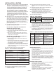
A4. Limit the total equivalent vent pipe length to fall between
the minimum and maximum equivalent vent lengths given
INSTALLATION - VENTING
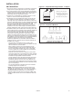
Figure 6.1 - Venting Through Combustible Roof or Wall
See Instruction A12 for attaching single wall pipe to double wall pipe.
Specified
Terminal
Flashing
Listed
Thimble
Specified
Terminal
Flashing
Clearance Specified
by Type B Vent Mfg.
Listed
Thimble
Single Wall Vent Pipe
Double Wall Vent Pipe
Single Wall Vent Pipe Terminating
with Double wall vent pipe.
Single Wall Vent Pipe
Double
Wall
Single
Wall
Specified
Terminal
Clearance Specified
by Type B Vent Mfg.
Single
Wall
Specified
Terminal
1. Gas fired heating equipment must be vented - do not
operate unvented.
2. A built-in power exhauster is provided - additional external
power exhausters are not required or permitted.
3. If an existing heater is being replaced, it may be
necessary to resize the venting systems. Improperly sized
venting systems can result in vent gas leakage or the
formation of condensate. Refer to the National Fuel Gas
Code ANSI Z223.1 (NFPA 54) or CSA B149.1 - latest
edition. Failure to follow these instructions can result in
serious injury or death.
4. Under no circumstances should two sections of double
wall vent pipe be joined together within one horizontal
vent system due to the inability to verify complete seal of
inner pipes.
CAUTION
Installation must conform with local building codes or in the
absence of local codes, with the National Fuel Gas Code,
ANSI Z223.1 (NFPA 54) - latest edition. In Canada installation
must be in accordance with CSA B149.1.
Model PDP and BDP unit heaters must be vented with the
proper passageway as described in these instructions to convey
flue gases from the unit or the vent connector to the outside
atmosphere.
The venting instructions are organized in sections, based on
installation type. The sections are identified as follows:
in Table 6.1, making the vent system as straight as
possible. The equivalent length of a 5" elbow is 6' and for a
6" elbow is 7'.
A5. A minimum of 12" straight pipe is recommended from the
flue outlet before turns in the vent pipe.
A6. Horizontal sections of vent pipe are to be installed with a
minimum downward slope from the appliance of 1/4" per
foot and suspended securely from overhead structures at
points not greater than 3' apart.
A7. Fasten individual lengths of vent together with at least
3 corrosion resistant sheet metal screws.
A8. Keep single wall vent pipe at least 6" from combustible
materials. For double wall vent pipe, follow the vent pipe
manufacturer’s clearances to combustibles. The minimum
distance from combustible materials is based on the
combustible material surface not exceeding 160°F.
Clearance from the vent pipe (or the top of the unit) may be
required to be greater than 6" if heat damage other than fire
could result (such as material distortion or discoloration).
A9. Avoid venting through unheated space when possible.
When venting does pass through an unheated space or
if the unit is installed in an environment that promotes
condensation, insulate runs greater than 5' to minimize
condensation. Inspect for leakage prior to insulating and
use insulation that is noncombustible with a rating of not
less than 400°F. Install a tee fitting at the low point of the
vent system and provide a drip leg with a clean out cap as
shown in Figure 8.1.
The differences between vertical and horizontal vent systems will be identified in
"Section A - General Instructions - All Units".
W
ARNING
Instructions
Applicable Installation Instructions
by Vent System Type
A General Instructions for ALL Installations
B VERTICAL CATEGORY I vent systems ➀
C HORIZONTAL CATEGORY III vent systems ➀
Model Vent Transition Vent Pipe Minimum Maximum
Size Included Diameter Eqv Length Eqv Length
150, 175 4" to 5" 5" 2' 60'
200 6" to 5" 5" 2' 60'
250-400 Not required 6" 2' 70'
Table 6.1 - Vent Pipe Diameters, Transitions, and
Total Equivalent Vent Pipe Lengths for Horizontal
Vent Systems