
Installation and Service Manual

1-552.8
5H70719A Rev. H
September, 2006
INSTALLATION INSTRUCTIONS
solid-state speed controller steam/hot water unit heaters
Application
For remote control of air delivery volume, solid-state speed
controllers are available for steam/hot water unit heaters,
models HS/HSB/HC and WTC/WSC, sizes 18 through 108 with
115V/60Hz/1ph, Power Code 01 motors. The controller adjusts
motor input voltage to maintain speed regulation at any setting
between “High” and “Low”. The control is rated for 5.0 Amps.
Installation and Wiring Connections
1. The speed controller must be field mounted to a standard 2”
x 4” junction box.
2. Disconnect power supply before making wiring connections
to prevent electrical shock and equipment damage.
3. Installation of wiring must conform with local building codes,
or in the absence of local codes, the National Electric Code
ANSI/NFPA 70 - Latest Edition. Unit must be electrically
grounded in conformance to this code. In Canada, wiring
must comply with CSA C22.1, Electrical Code.
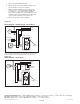
4. The unit must be wired strictly in accordance with the wiring
diagram furnished with the unit. Any wiring different from
the wiring diagram could result in a hazard to persons and
property. See Figure 2.1 or 2.2 for the applicable wiring
diagram, by unit heater motor size.
Operation Check
1. Once the unit, thermostat, and speed controller have been
installed, set the thermostat to the lowest setting and the
speed controller to minimum speed.
2. Turn on the power to the system.
3. Adjust the thermostat above room temperature. The motor
should start on low speed. If the motor does not start, two
possible reasons are:
a. Check power supply and wiring to ensure the unit is wired
properly and the power turned on.
b. The speed controller has a factory-set minimum set point.
If the unit motor does not start at this minimum set point,
the minimum set point may be adjusted. See step 4 for
instructions.
4. Adjust the speed controller to select the desired fan speed. If
a larger speed range is required, the factory-set minimum set
point can be adjusted as outlined in the following steps. Note
that on new motors, bearings may be slightly tight until motor
is “broken-in”. Do not adjust speed controller below minimum
speed level until motor has experienced some running time.
THIS MANUAL IS THE PROPERTY OF THE OWNER.
PLEASE BE SURE TO LEAVE IT WITH THE OWNER WHEN YOU LEAVE THE JOB.
Appliances with Power Code 01 must not be installed
where they may be exposed to a potentially explosive
or flammable atmosphere.
DANGER
cAutioN
Do not reuse any electrical component which has been
wet. Such component must be replaced.
1. Disconnect power supply before making wiring
connections to prevent electrical shock and
equipment damage.
2. All appliances must be wired strictly in accordance
with wiring diagram furnished with the appliance.
Any wiring different from the wiring diagram could
result in a hazard to persons and property.
3. All wiring must be done with wiring material having a
temperature rating of at least 105°C.
WARNiNG
The use of this manual is specifically intended for a
qualified installation and service agency and is to be
used in conjunction with the unit heater installation and
service manual. All installation and service of these
units must be performed by a qualified installation
and service agency. Manuals may contain excerpts
from component supplier literature adapted for these
products. Any accompanying component supplier
literature is for general information.
iMPoRtANt