
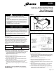
Installation and Service Manual

Description
The 240/25 or 208/25 volt transformer relay is rated for
resistive loads up to 6000 watts or motor loads up to twelve
amps. Units with 480V supply voltage (33 power code) come
standard with a 480V to 240V transformer making the low
voltage control kit compatible with power code 33. Wiring of
this control kit should only be performed by a qualified
electrician.
Installation and Wiring - HER models
1. Disconnect power supply before making wiring connections
to prevent electrical shock and equipment damage. All
units must be wired strictly in accordance with wiring
diagram furnished with the unit.
2. Open the hinged bottom panel.
3. Insert the transformer relay lead wires into the control
wiring hole in the back panel.
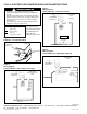
4. Fasten the transformer relay to the back panel with the
locknut, as shown in Figure 1.
5. Wire transformer relay per Figure 2. Be sure to connect
yellow wire to fan motor lead not attached to control
terminal block. Refer to wiring diagram on inside of bottom
pan.
Any damage to, or failure of Modine units caused by
incorrect wiring of the units is not covered by Modine’s
standard warranty.
Installation and Wiring -
VE and PTE models
1. Disconnect power supply before making wiring connections
to prevent electrical shock and equipment damage. All units
must be wired strictly in accordance with wiring diagram
furnished with the unit.
2. Remove cover from power junction box.
3. Insert the transformer relay lead wires into the control
wiring hole in the power junction box.
4. Fasten the transformer relay to the power junction box with
the locknut.
5. Wire the transformer relay per Figures 4, 5, or 6. Refer to
wiring diagram on inside of power junction box cover.
6. For the VE & PTE 300, 400, and 500 only, a jumper wire
(14 ga. minimum) must be added between the “L” and “H”
terminals of the control terminal block.
Part Number
Description 240/25V 208/25V
Transformer Relay 5H70983B1 5H70983B2
Figure 1
Installation - HER models
Figure 2
Wiring Diagram - HER models
December, 2001
INSTALLATION INSTRUCTIONS
low voltage control
electric unit heaters
2-518.5
5H70984A Rev. C
FROM POWER
SUPPLY
TO CONTACTOR COIL
OR LIMIT CONTROL
CONNECT TO SAME
TERMINAL AS FAN
MOTOR LEAD
NOT ATTACHED
TO CONTROL
TERMINAL BLOCK
TO LOW VOLT
THERMOSTAT
TRANSFORMER
RELAY
YL BK BU
CONTROL
TERMINAL
BLOCK
WIRING LEGEND
FIELD WIRING
FACTORY WIRING
• WIRE NUT
* SUPPLIED BY
OTHERS
ALL WIRING MUST COMPLY WITH NATIONAL
ELECTRIC CODES AND ALL LOCAL CODES.
ALL COMPONENTS MUST AGREE WITH THEIR
RESPECTIVE POWER SOURCE.
LOCKNUT
TRANSFORMER
RELAY
Page 1 of 2
WARNING
1. Disconnect power supply before making wiring
connections to prevent electrical shock and equipment
damage.
2. All units must be wired strictly in accordance with wiring
diagram furnished with the unit. Any wiring different from
the wiring diagram could result in a hazard to persons
and property.
3. All wiring must be done with a wiring material having a
temperature rating of at least 105°C.
IMPORTANT
The use of this manual is specifically intended for a qualified
installation and service agency. All installation and service of
these units must be performed by a qualified installation and
service agency. Modine manuals may contain excerpts from
component supplier literature adapted for Modine products.
Any accompanying component supplier literature is for
general information.