6-189.6 August, 2011 Gas-Fired Power Vented Unit Heaters Propeller & Blower Models MODEL HD MODEL HDB MODEL PDP MODEL BDP 6-189.
TABLE OF CONTENTS Modine’s power vented unit heaters are designed for the heating requirements of commercial and industrial buildings with select models available for residential garage heating as well. For locations where negative pressure may be an issue or energy savings over older gravity vented units may be desired, Modine power vented gas fired unit heaters are your solution.
DESIGN FEATURES - ALL UNITS Tubular Heat Exchanger Power Vented Unit Heaters, 30-125MBH For residential, commercial or industrial applications that require a low profile unit, Modine offers the Hot Dawg®. Capable of being installed just one inch below the ceiling, the superior quality of the Hot Dawg makes it a preferred choice for a variety of applications, including garages and workshops. Figure 2.
DESIGN FEATURES - MODELS HD/HDB Figure 4.1 - Factory Mounted Standard and Optional Features (Models HD/HDB) ➃ ➅ ➉ ➇ ➁ ➀ ➂ ➈ ➄ ➀ Power Exhauster (STD) All HD series (low profile) unit heaters are supplied with a round vent pipe connection. ➁ Pressure Switch (STD) An automatic reset vent pressure switch is supplied on all HD series (low profile)unit heaters and is designed to prevent operation of the main burner in the event there is restricted venting of flue products.
DESIGN FEATURES - MODELS PDP/BDP Figure 5.1 - Factory Mounted Standard and Optional Features (Models PDP/BDP) ➈ ➉ ➆ ➁ ➇ ➄➂ ➅ ➃ ➀ All units include the standard (STD) features, and may include the optional (OPT) features shown. ➀ Gas Valve (See Table 12.2) a) Single Stage Gas Valve - (STD) The main gas valve is factory installed on the unit heater gas train. The main gas valve provides the pilot, regulator, main gas, and manual shutoff functions.
GENERAL PERFORMANCE DATA - MODELS HD & PDP Table 6.
general performance data - MODELS HDB & BDP Table 7.
BLOWER performance data - MODEL HDB Table 8.1 - Power Code Description - HDB Models Power Code 01 Unit Voltage 115/60/1 HDB60 HDB75 HDB100 HDB125 1/4 HP 1/3 HP 1/2 HP 1/2 HP Blower Speed Curves Models (HDB 60-125) Low Medium High 684 60 741 55 808 50 889 45 988 40 1111 35 0.00 1270 0.10 0.20 0.30 0.40 0.50 0.60 65 1140 60 1235 55 1347 50 1481 45 1646 40 1852 35 0.00 0.70 2116 0.10 0.20 External Static Pressure (IN. WC) 0.50 0.60 0.70 0.
BLOWER performance data - MODEL BDP Table 9.
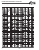
BLOWER PERFORMANCE DATA - MODEL BDP Blower Model BDP 175 200 250 300 350 400 1.5 475 1/3 95 5.0 535 375 2.5 445 0.5 505 191 60 1852 345 3.5 420 65 1709 315 4.0 400 70 1587 295 5.0 40 3241 805 1-1/2 193 3.5 45 2881 715 1 50 2593 645 3/4 55 2357 585 1/2 96 60 2160 540 65 1994 495 1/3 95 70 1852 460 40 45 50 3704 3292 2963 420 375 335 55 60 65 70 40 45 2694 2469 2279 2116 4630 4115 50 1/4 3/4 1/2 1/3 192 16 101 1.0 485 2.0 470 380 2.
BLOWER PERFORMANCE DATA - MODEL BDP Blower Model BDP Filters Models With or Without Blower Enclosure ➀ ➁ For blower units with enclosure and filter, add the following static pressures to the static pressure determined by the system designer for total external static pressure. Data for use with filters only 150 40 2778 750 45 2469 715 50 2222 685 55 2020 665 60 1852 650 65 1709 640 70 1587 630 40 3241 970 2 45 2881 900 1-1/2 50 2593 845 1 38 3/4 1.5 - 2.0 755 2.
GAS CONTROL DATA - ALL MODELS Table 12.
ACCESSORIES Table 13.1 - Field Installed Accessories Model Controls Cabinet and Air Mover Feature HD HDB PDP BDP Vertical Deflector Blades - Allows directional discharge air control in the left and right directions. • • • • Downward Air Deflector Hoods - Available in 30°, 60°, and 90° configurations these deflector hoods enable the unit to be mounted higher while still providing heat to the building occupants. Refer to page 14 for further details.
PERFORMANCE DATA - HOODS FOR PROPELLER MODELS Table 14.
PERFORMANCE DATA - VELOCITY GENERATING NOZZLES Figure 15.1 - Velocity Generating Nozzles 40° DOWNWARD NOZZLE ➀ H T S 90° VERTICAL NOZZLE H S S 5-WAY NOZZLES T 40° SPLITTER NOZZLE T S H S S ➀ Velocity generating nozzles available for Blower Model BDP only. Table 15.1 - Blower Unit Model BDP Velocity Generating Nozzle Performance Data (feet) ➁ BDP Blower Model Size Nozzle Type 40° Downward Nozzle 90° Vertical Nozzle 40° Splitter Nozzle 5-Way Nozzle Max. Mounting Ht. (ft.
UNIT SELECTION Selection Procedure In order to properly select a unit heater it is necessary to have the following basic information. 1. Heating output capacity Model size output is to be matched against the heat loss to be replaced. 2. External static pressure (blower units only) The external static pressure (E.S.P.) is determined using the ASHRAE Guide for duct losses or provided by the design engineer. 3. Accessory internal static pressure (Nozzles, transitions, filters, etc.
UNIT SELECTION Selection Example Conditions (Blower Unit) In the following example, select a unit heater to meet the following conditions: 1. Heating output capacity = 156,000 Btu/Hr per design engineer 2. External Static Pressure = 0.2. 3. Internal Static Pressure = 0.0. No static producing accessories are required 4. Heat exchanger and burner = Aluminized Steel 5. Gas Type = Propane 6. Gas Controls = Two stage Intermittent Pilot 7. Supply Voltage: 230V/60Hz/3Ph 8. Altitude: 1,000 feet 9.
DIMENSIONAL DATA - MODEL HD/HDB Propeller Units - Model HD Blower Units - Model HDB Figure 18.1 - Dimensional Drawings - Model HD Figure 18.2 - Dimensional Drawings - Model HDB 3/8"-163/8"-16 MOUNTING HOLESHOLES 14.9" BETWEEN MOUNTING MOUNTING HOLESHOLES TYP TYP14.9" BETWEEN MOUNTING (MODEL SIZES 100 AND 125 ONLY) (MODEL SIZES 100 AND 125 ONLY) 3/8 x 1"3/8 LONG x 1" LONG G G 3.5" 14.9" BETWEEN 3/8"-163/8"-16 MOUNTING HOLESHOLES 14.
DIMENSIONAL DATA - MODEL PDP Propeller Units - Model PDP Figure 19.1 - Dimensional Drawings M C A H F CC X W K AA DD G J K E B LL BB EE L (MIN. DISTANCE TO WALL) D (OPENING) Table 19.1 - Dimensions (inches) - PDP ➀ Dimension Symbol Figure 19.
DIMENSIONAL DATA - MODEL BDP Blower Units - Model BDP Figure 20.1 - Dimensional Drawings C A N F H W EE DD CC X J K DD CC S 5 9/16" P J 5 9/16" O G AA 3/4" G K E QxV B RxT BB D (OPENING) BLOWER FILTER RACK ENCLOSURE (OPTIONAL) (OPTIONAL) L (MIN. DISTANCE TO WALL) M (APPROX.) L (MIN. DISTANCE TO WALL) Table 20.
SPECIFICATIONS - ALL MODELS E.2.a. The heat exchanger(s) seams and duct connections shall be certified to withstand 0.5" W.C. external static pressure without burner flame disturbance. (PDP/BDP models) General A. Standards All unit(s) shall include: A.1. E.3. C.S.A. (Canadian Standards Association) design certification for use in both the US and Canada to the ANSI Z83.8 - latest revision, standard for “Gas Unit Heater and Gas-Fired Duct Furnaces” for safe operation, construction, and performance. B.
SPECIFICATIONS - ALL MODELS J.5. An Energy Saver Kit used to reduce stratified air in high mounting height applications. (PDP/BDP models) The motor wiring shall be in flexible metal BX conduit. J.7. Vertical Deflector Kit to enable side distribution of airflow. G.3. (opt) The motor shall be controlled by a time delay relay (opt) and motor starter. J.8. A blower enclosure fully encloses blower to enable the attachment of filter racks and/or duct. G.4.
model nomenclature Figure 23.
The Modine brand has been the Products from Modine are designed to provide indoor air-comfort solutions industry standard since Arthur B. for commercial, institutional and industrial applications. Whatever your heating, Modine invented and patented ventilating and cooling requirements, Modine has the product to satisfy your needs, including: the first lightweight, suspended hydronic unit heater in 1923.