
Overview of Primary Product


22
6-189.6
SPECIFICATIONS - ALL MODELS
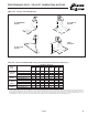
G. Air Mover
G.1. The motor horsepower shall be ____.
G.2. The motor wiring shall be in flexible metal BX conduit.
G.3. (opt) The motor shall be controlled by a time delay relay (opt)
and motor starter.
G.4. Propeller models shall meet the following requirements.
G.4.a. The motor type shall be Single-speed, Totally Enclosed (TE)
(Open Drip Proof (ODP) on HD units 75MBH and smaller)
G.4.b. The motor shall be rated for:
(a) 115V/60Hz/1Ph
(b) 208V/60Hz/1Ph (PDP model)
(c) 230V/60Hz/1Ph (PDP model)
G.5. Blower models shall meet the following requirements.
G.5.a. The motor type shall be Single-speed, totally enclosed (TE)
(Open Drip Proof (ODP) on all HDB units)
G.5.b. The motor shall be rated for:
(a) 115V/60Hz/1Ph
(b) 208V/60Hz/1Ph (BDP model)
(c) 230V/60Hz/1Ph (BDP model)
(d) 208V/60Hz/3Ph (BDP model)
(e) 230V/60Hz/3Ph (BDP model)
(f) 460V/60Hz/3Ph (BDP model)
(g) 575V/60Hz/3Ph (BDP model)
G.5.c. The motor shall be provided with an adjustable motor sheave to
allow for minor adjustment of the blower rpm at the job site.
(BDP model)
G.5.d. The blower shall be a double width, double inlet (DWDI), forward
curved, belt driven, assembly with spider ball bearings.
G.5.e. The motor shall be provided with three speed taps to allow for
adjustment of the blower rpm at the job site. (HDB model)
G.5.f. The blower shall be a double width, double inlet (DWDI), forward
curved, direct motor drive assembly with spider ball bearings.
(HDB model)
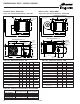
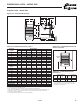
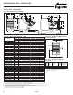
H. Mounting
H.1. The unit shall be equipped with tapped holes to accept 3/8-16
threaded rod for suspension. (HD/HDB size 100/125 and PDP/
BDP models)
H.1.a. The unit shall be equipped with mounting brackets to allow for
threaded rod suspension or to be bolted directly to the ceiling
support structure allowing 1" of top clearance. (HD/HDB models -
opt on sizes 100/125)
H.2. Propeller Unit (Sizes 150 – 300) to have two point adjustable
suspension points to allow for level hanging with a variety of
accessories.
H.3. Propeller unit (Sizes 30-75 and 350-400) and blower units
(Sizes 60-300) to have 4 suspension points.
H.4. Blower unit (Sizes 350, 400) to have 6 suspension points.
J. Accessories
The following field installed accessory control devices shall be
provided with the unit:
J.1. A 5-50 psi gas pressure regulator to reduce the inlet gas
pressure for the operating controls.
J.2. A clear plastic thermostat guard with two keys for room
thermostats.
J.3. A SPST summer winter switch for continuous fan in the summer
position and intermittent fan and burner in the winter position.
J.4. Pipe Hanger Adapter Kit to facilitate threaded pipe suspension.
(HD/HDB size 100/125 and PDP/BDP models)
J.5. An Energy Saver Kit used to reduce stratified air in high mounting
height applications. (PDP/BDP models)
J.7. Vertical Deflector Kit to enable side distribution of airflow.
J.8. A blower enclosure fully encloses blower to enable the
attachment of filter racks and/or duct.
J.9. A combination filter rack/duct connector containing a 1" thick,
cleanable filter.
J.11. A belt guard enclosing the belts and sheaves (pulleys) on a
blower type unit heater. (BDP model)
J.12. Propane conversion kit for converting natural gas units to
propane gas.
J.13. 40° downward double deflection velocity generating discharge
nozzle. (BDP model)
J.14. 40° splitter double deflection velocity generating discharge
nozzle. (BDP model)
J.15. 90° vertical double deflection velocity generating discharge
nozzle. (BDP model)
J.16. 5-way downward velocity generating discharge nozzle.
(BDP model)
J.17. Discharge Transition from unit to polytube. (HDB/BDP models)
J.18. 30° non-velocity generating downward air deflector hood
constructed of 20 ga. cold rolled steel with baked-on gray-green
polyester powder paint.
J.19. 60° non-velocity generating downward air deflector hood
constructed of 20 ga. cold rolled steel with baked-on gray-green
polyester powder paint.
J.20. 90° non-velocity generating downward air deflector hood
constructed of 20 ga. cold rolled steel with baked-on gray-green
polyester powder paint.
J.21. (opt) A 208V to 115V step down shall be provided for operation
of the propeller unit.
J.22. (opt) A 230V to 115V step down shall be provided for operation
of the propeller unit.
J.23 (opt) A 460V to 115V step down shall be provided for operation
of the propeller unit.
J.24. (opt) A 575V to 115V step down shall be provided for operation
of the propeller unit.
K. Thermostats
The unit shall be provided with the following thermostat:
K.2. A single stage room thermostat with a 50°-90°F range.
K.3. A single stage room thermostat with a 50°-90°F temperature set
point range. The stat shall also include switching for Heat/Off and
Fan On/Auto control.
K.4. Honeywell TH5220D1029 digital non-programmable configurable
room thermostat with switching.
K.5. A field installed two-stage duct thermostat with a 0°-100°F range
and 20-foot capillary.
K.6. A two-stage electronic duct thermostat with field installed
temperature sensor, temperature selector and one stage adder.