
Installation and Service Manual

26
6-580.12
General Maintenance
The unit and venting system must be checked once a year by
a qualified service technician.
All installation and service of these units must be
performed by a qualified installation and service agency.
Before any service, BE SURE TO TURN OFF GAS AT THE
MANUAL SHUT-OFF VALVE AHEAD OF THE COMBINATION
GAS CONTROL AND TURN OFF ALL ELECTRIC POWER
TO THE HEATER.
General Unit
When providing annual maintenance for the unit heater, keep
the unit free from dust, dirt, grease and foreign matter. Pay
particular attention to:
1. The combustion air and exhaust vent piping.
2. The burner ports and pilot burner orifices (avoid the use of
hard, sharp instruments capable of damaging surfaces for
cleaning these ports). To check the burner port and pilot
burner orifice, see “Burner and Pilot Assembly Removal”.
3. The air shutters and main burner orifices (avoid the use of
hard, sharp instruments capable of damaging surfaces for
cleaning these orifices). To check the air shutters and main
burner orifices, see for “Manifold Assembly Removal.”
4. The heat exchanger. Clean tubes from the bottom with a
stiff non-wire brush.
5. The heat exchanger should be checked annually for cracks
and discoloration of the tubes. If a crack is detected, the
heat exchanger should be replaced before the unit is put
back into service. If the tubes are dark gray, airflow across
the heat exchanger should be checked to insure that a
blockage has not occurred or the blower is operating
properly.
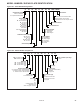
Electrical Wiring
The electrical wiring should be checked annually for loose
connections or deteriorated insulation.
MAINTENANCE
CAUTION
1. Service or repair of this equipment must be performed by a
qualified service agency.
2. Do not attempt to reuse any mechanical or electrical
controllers which have been wet. Replace defective controller.
WARNING
When servicing or repairing this equipment, use only factory-
approved service replacement parts. A complete replacement
parts list may be obtained by contacting the factory. Refer to
the rating plate on the appliance for complete appliance model
number, serial number, and company address. Any substitution
of parts or controls not approved by the factory will be at the
owner’s risk.
Gas Piping & Controls
The gas valves and piping should be checked annually for
general cleanliness and tightness.
The gas controls should be checked to ensure that the unit is
operating properly.
Propeller Assembly
Check the motor for lubrication if the motor is not permanently
lubricated. Inspect the fan for damage and fit on motor shaft.
Clean any dust, dirt or foreign matter from the fan blades.
Blower Assembly
The blower assembly includes the bearings, drive sheaves and
belts. Blower bearings should be checked and lubricated based
on the blower manufacturer’s recommendations. Bearings
should also be checked for any unusual wear and replaced if
needed.
Drive sheaves should be checked at the same time the
bearings are inspected. Check to make sure the sheaves are
in alignment and are securely fastened to the blower and motor
shafts.
Belt tension should be rechecked shortly after the unit has been
installed to check for belt stretching. After the initial start-up,
monthly checks are recommended.
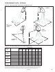
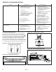
Manifold Assembly Removal
To remove the manifold:
1. Shut off gas and electric supply.
2. Lower bottom pan to expose burner and manifold (see
Figure 16.2).
3. Disconnect pilot tubing and thermocouple lead (or ignition
cable) at the combination gas control (and ignition control).
4. Disconnect control wires for the combination gas control.
5. Disconnect gas manifold at ground union joint.
6. Remove the 2 screws holding the manifold to the heat
exchanger support.
7. Clean the orifices and adjust the air shutters as necessary.
8. Follow steps 2-6 in reverse order to install the manifold
assembly.
9. Turn on the electric and gas supply.
10. Check the ground union joint for leaks with a soap
solution. Tighten if necessary.
Burner and Pilot Assembly Removal
To remove the burner:
1. Shut off gas and electric supply.
2. Lower bottom pan to expose burner and manifold (see
Figure 16.2).
3. Disconnect pilot tubing and thermocouple lead (or ignition
cable) at the combination gas control (and ignition control).
4. Remove the 2 burner retaining pins holding the burner in
place. The burner can then be easily lowered from the unit.
5. Examine the burner and pilot assembly for cleanliness
and/or obstructions as necessary (see “General Unit” for
cleaning instructions).
6. Replace the burner assembly in reverse order. In replacing
the burner, be certain that the slots at the front of the
burner are located properly on their shoulder rivets and
that the burner retaining pins are put back into their proper
locations.
7. Reconnect the ignition cable and pilot gas supply line.
8. Turn on the electric and gas supply.
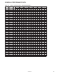
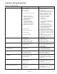
NOTE: To check most of the possible remedies in the
troubleshooting guide listed in Table 27.1, refer to the applicable
sections of the manual.