
Installation and Service Manual


9
6-580.12
Section C – Horizontal, Category III Vent System
Installation
C1. This section applies to horizontally vented Category III
vent systems and is in addition to “Section A – General
Instructions – All Units”.
C2. Horizontal vent systems terminate horizontally (sideways).
C3. Seal all seams and joints of un-gasketed single wall pipe
with metal tape or Silastic suitable for temperatures up to
400°F. Wrap the tape 2 full turns around the vent pipe.
For single wall vent systems, 1 continuous section of
double wall vent pipe may be used within the vent system
to pass through the wall to the listed vent cap.
Under no
circumstances should two sections of double wall vent pipe
be joined together within one horizontal vent system due to
the inability to verify complete seal of inner pipes.
Category
III vent systems listed by a nationally recognized agency and
matching the diameters specified may be used. Different
brands of vent pipe materials may not be intermixed. Refer
to instruction A10 in “Section A – General Instructions – All
Units” for attaching double wall pipe to single wall pipe.
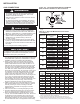
C4. Refer to Table 9.1 for total minimum and maximum vent
lengths, making the system as straight as possible. The
equivalent length of a 90° elbow is 6' for 5" diameter and
7' for 6" diameter.
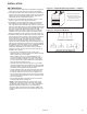
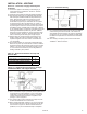
C5. All horizontal Category III vents must be terminated with a
listed vent cap. The cap must terminate a minimum distance
beyond the exterior wall surface as shown in Figure 9.2 and
Table 9.1. The vent must be supported as shown in Figure
9.1. Precautions must be taken to prevent degradation of
building materials by flue products.
C6. When condensation may be a problem, the vent system shall
not terminate over public walkways or over an area where
condensate or vapor could create a nuisance or hazard or
could be detrimental to the operation of regulators, relief
openings, or other equipment.
C7. The venting system must be exclusive to a single unit, and
no other unit is allowed to be vented into it.
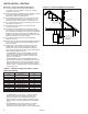
C8. When vented horizontally, maintain a 1/4" per foot rise away
from the heater and place a drip leg with clean out near the
unit as shown in Figure 9.2. Where local authorities have
jurisdiction, a 1/4” per foot downward slope is acceptable
with a drip leg and clean out near the exit of the vent as
shown in Figure 9.2, or allow the condensate to drip out
the end.
C9. For a vent termination located under an eave, the distance
of the overhang must not exceed 24". The clearance to
combustibles above the exterior vent must be maintained
at a minimum of 12". Consult the National Fuel Gas Code
for additional requirements for eaves that have ventilation
openings.
C10. Once venting is complete, proceed to the section titled
“Installation – Gas Connections”.
INSTALLATION - VENTING
Figure 9.2 - Horizontal Venting
Figure 9.1 - Exhaust Vent Construction Through
Combustible Walls and Support Bracket
Table 9.1 - Dimension Between Vent Cap and
Exterior Wall
Vent Terminal “A” Min.
Selkirk, Starkap, or Constant Air-Flo 2433 12"
Gary Metals 1092 or Modine 5H072285 6"
Tjernlund VH1 0"