
Installation and Service Manual

5
6-580.12
INSTALLATION
UNIT MOUNTING
1. Be sure the means of suspension is adequate to support the
weight of the unit (see pages 24 and 25 for unit weights).
2. For proper operation and to assure that flames are directed
into the center of the heat exchanger tubes, the unit must be
installed in a level horizontal position. Use a spirit level to
ensure that the unit is suspended correctly.
3. Clearances to combustibles as specified in Figure 4.1 and
Ta bles 4.1 and 4.2 must be strictly maintained.
4. All standard units are shipped fully boxed. Larger units are
also supplied with skid supports on the bottom of the box.
The larger units may be lifted from the bottom by means of a
fork lift or other lifting device only if the shipping support skids
are left in place and the forks support the whole depth of the
unit. If the unit must be lifted from the bottom for final
installation without the carton in place, be sure to properly
support the unit over its entire length and width to prevent
damage. When lifting units, make sure the load is balanced.
5. Propeller models up to size 350 have 2 mounting holes, size
350 and above have 4 mounting holes and blower models up
to size 350 have 4 mounting holes, size 350 and above
have 6 mounting holes. Units with two point suspension
incorporate a level hanging feature. Depending on what
options and accessories are being used, the heater may not
hang level as recieved from the factory. Do not hang heaters
with deflector hoods until referring to the “Installation Manual
for Deflector Hoods” and making the recommended
preliminary adjustments on the heater, while the heater is
resting on the floor. The units can be mounted with 3/8"-16
threaded rod as follows:
•Oneachpieceofthreadedrodused,screwanuta
distance of about 1" onto the end of the threaded rods that
will be screwed into the unit heater.
•Placeawasherovertheendofthethreadedrodand
screw the threaded rod into the unit heater weld nuts on
the top of the heater at least 5 turns, and no more than
10 turns. Tighten the nut first installed onto the threaded
rod to prevent the rod from turning.
•Drillholesintoasteelchannelorangleironatthesame
center-line dimensions as the heater that is being installed.
The steel channels or angle iron pieces need to span and
be fastened to appropriate structural members.
•Cutthethreadedrodstothepreferredlength,placethem
through the holes in the steel channel or angle iron and
secure with washers and lock nuts or lock washers and
nuts. A double nut arrangement can be used here instead
of at the unit heater (a double nut can be used both places
but is not necessary).
•Donotinstallstandardunitheatersabovethemaximum
mounting height shown in Table 19.1.
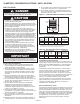
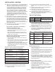
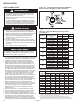
NOTE: A pipe hanger adapter kit, shown in Figure 5.2 is
available as an accessory. One kit consists of two drilled
3/4" IPS pipe caps and two 3/8" - 16 x 1-3/4" capscrews to
facilitate threaded pipe suspension. Two kits would be
required for PDP unit sizes 350 and 400 and all BDP units
except size 350 and 400, and 3 kits for BDP unit sizes 350
and 400.
Figure 5.2 - Suspension Methods
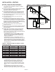
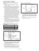
1. Remove outer side panels.
2. “Set screws” - loosen and
position bracket where needed
– then tighten set screws.
3. Re-attach outer side panels.
Figure 5.1 - Adjustable Mounting Brackets - To Adjust:
(Suspension with Pipe Adapter Kit)