
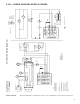
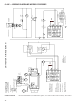
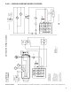
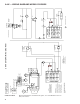
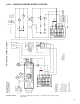
Wiring Diagram

14
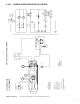
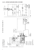
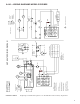
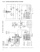
6-446 — WIRING DIAGRAMS MODELS PDP/BDP
W
Automatic
Gas Control
D
Mechanical
Modulating
Gas Control
D
Y
Automatic Gas
Control
Fan
Motor
L3
L2
L1
Circuit Breaker
(By Others)
L1 L2 L3
230V/60Hz/3Ø Power Shown
Starter
Coil
Starter
Overload
V
T1
G
C
Xfmr
230V
24V
T2
Limit
Control
Indicates Terminal Board Connection
Pressure
Switch
Power
Exhaust
Motor
Mechanical
Modulating
Gas Control
D
D
Note to installer:
Attach this diagram near heater.
All wiring must comply with national
electric code and all local codes.
All components must agree with
their respective power source.
Use 105° wire for replacements.
Caution
Failure to wire this unit according
to this wiring diagram may result
in injury to the installer or user.
For deviations contact the factory.
* Alternate Xfmr.
Primary Xfmr Wires
230V/60Hz/1Ø-BK & Y (OR O)
200V/60Hz/1Ø-BK & R
Wire nut the wire not used.
3 Phase
Starter
(By Others)
* 24V
Xfmr
Pressure
Switch
W
230V/60Hz/3Ø Power Shown
Circuit Breaker
(By Others)
L1
L2
L3
BK
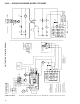
Factory
Field
Wire Nut
24V.Line
Wiring Legend
C
L3L2
L1
Fan
Motor
T3T2T1
BL
J-Bo
x
Te rm i na l
Board
O
BK
BL
BL
BL
G
V
F
C
T2
T1
R
BL
Limit
Control
Gnd
Power
Exhaust
Motor
UNIT HEATER WIRING DIAGRAM
BK
R
BL
Y
W
G
O
Ignitor
R
BL
Y
W
G
O
Ignitor
R
BL
Y
W
G
O
Ignitor
BK
Ignitor
ROBERTSHAWHONEYWELL
MV
MV
SPARK
24V
PV
MV/PV
24V
(GND)
GND
PV
SPARK
PV/MV
TR(GND)
GND
ROBERTSHAWHONEYWELL
MV
MV
SPARK
24V
PV
MV/PV
24V
(GND)
GND
TH(24V)
PV
SPARK
PV/MV
TR(GND)
GND
ROBERTSHAWHONEYWELL
MV
MV
SPAR
K
24V
PV
MV/PV
24V(GND)
GND
PV
SPAR
K
PV/MV
TR(GND)
GND
ROBERTSHAWHONEYWELL
MV
MV
SPAR
K
24V
PV
MV/PV
24V(GND)
GND
TH(24V)
PV
SPAR
K
PV/MV
TR(GND)
GND
IGNITION CONTROLLERIGNITION CONTROLLER
IGNITION CONTROLLERIGNITION CONTROLLER
Some models may have limit control
to pressure switch wire routed outside
of J-box.
5H78233C4 REV A Mechanical Modulation, Intermittent Pilot Ignition, 100% Shut-Off with Continuous
Retry, Three-Phase.