
Wiring Diagram


18
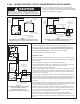
6-446 — WIRING DIAGRAMS MODELS PDP/BDP
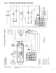
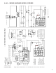
5H78233B9 Single-Stage, Standing Pilot Ignition, 100% Shut-Off, Three-Phase.
TD Relay
TDC
TD Relay
TDC
ECO
TR
Combination
Gas
Control
TH
Pressure
Switch
Limit
Control
V
Pressure
Switch
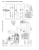
UNIT HEATER WIRING DIAGRAM
Wiri
ng Legend
Line 24V.
Factory
Field
Wire Nut
Caution
Failure to wire this unit according
to this wiring diagram may result
in injury to the installer or user.
For deviations contact the factory.
Note to installer:
Attach this diagram near heater.
All wiring must comply with national
electric code and all local codes.
All components must agree with
their respective power source.
Use 105° wire for replacements.
Indicates Terminal Board Connection
31
O.L.C.
2
4
T2
F
C
Xfmr
H1
H2H3
H4
X1
X2 X3
X4
460V
230V
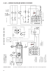
460V/60Hz/3ØPower Shown
Fan
Motor
L1 L2 L3
Circuit Breaker
(By Others)
L1 L2 L3
Starter
Coil
H
H
TD Relay
Heater
Therm
t°
230V
Xfmr
24V
T1
G
Power
Exhaust
Motor
Power
Exhaust
Motor
2
4
H
H
T-D Relay
3
1
R
Gnd
Limit
Control
BL
R
T1
T2
C
F
V
G
BL
W
Terminal
Board
24V
Xfmr
J-Box
BL
Low
Volt
Therm
(By Others)
R
T1 T2 T3
Fan
Motor
L1 L2
L3
C
OR
BK
Xfmr
H1
H2H3
H4
X1
X2 X3
X4
460V
230V
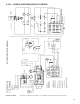
460V/60Hz/3Ø Power Shown
Circuit Breaker
(By Others)
L2
L1
L3
BK
Y
R
3 Phase
Starter
(By Others)
Xfmr
H1
H2
To L 2
X2
X3
To L 1
575V
230V
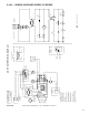
Alternate Wiring For Entrance J-Box
575V Transformer
To 24V Xfmr "BK"
To 24V Xfmr "O or R"
BK Y
To
Starter
Coil
R
BL
X4 X1
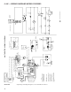
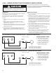
ECO
Connection
ECO
TH TR
Gas Control
Combination
Gas Control
Combination
Alternate
TR
TH
Switch
Pressure
Connectio
ns
ECO
ECO
Ter mi na l
Board "G"
Connections
ECO
Board "G"
Ter mi na l
Switch
Pressure
Gas Control
Combination
Alternate
ECO
TR
TH
Some models may have limit control
to pressure switch wire routed outside
of J-box.