
Wiring Diagram
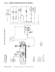
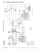
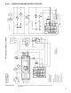

7
6-446 — WIRING DIAGRAMS MODELS PDP/BDP
5H78233C12 REV A Two-Stage, Standing Pilot, 100% Shut-Off, Single-Phase.
J-Box
R
2
4
H
H
T-D Relay
Switch
Pressure
Gnd
BL
T1
T2
C
F
V
G
BL
BL
BL
BK
W
W
Board
Terminal
XFMR
* 24V
3
1
BK
W
Motor
Exhaust
Power
Fan
Motor
Limit
Control
R
BL
Some models may have limit control
to pressure switch wire routed outside
of J-box.
Wiring Legend
Line
24V.
Factory
Field
Wire Nut
* Alternate Xfmr.
Primary Xfmr Wires
230V/60Hz/1Ø-BK & Y (OR O)
200V/60Hz/1Ø-BK & R
Wire nut the wire not used.
Caution
Failure to wire this unit according
to this wiring diagram may result
in injury to the installer or user.
For deviations contact the factory.
Note to installer:
Attach this diagram near heater.
All wiring must comply with national
electric code and all local codes.
All components must agree with
their respective power source.
Use 105°C wire for replacements.
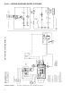
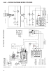
UNIT HEATER WIRING DIAGRAM
Indicates Terminal Board Connection
Low-Stage
Operator
Two-Stage
Therm
t°
TD Relay
Heater
H
H
Pressure
Switch
Limit
Control
T2
F
C
t°
High
Low
BA
High-Stage
Operator
C
TR
TH
ECO
115V/60Hz/1Ø Power Shown
Circuit Breaker
(By Others)
Second Circuit
Breaker Req'd.
For 230V,200V,1Ø
L1(BK)
L2(W)
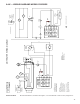
Circuit Breaker
(By Others)
Second Circuit
Breaker Req'd.
For 230V,200V,1Ø
115V/60Hz/1Ø Power Shown
L1
(BK)
L2
(W)
T1
G
Xfmr
115V
24V
V
BA
TH T
R
W
Combination
Gas Control
ECO
Connection
ECO
Combination
Gas Control
(By Others)
Therm
Low Volt
Two-Stage
C
Low High
Fan
Motor
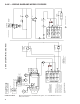
TDC
2
4
TD Relay
TD Relay
Power
Exhauster
Motor
3
1
TDC