
Installation and Service Manual

14
6-580.12
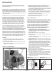
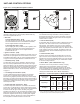
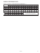
3. Adjust motor adjusting screw for a belt deflection of
approximately 3/4" with five pounds of force applied midway
between the sheaves (see Figure 14.3). Since the belt
tension will decrease dramatically after an initial run-in period,
it is necessary to periodically re-check the tension. Excessive
tension will cause bearing wear and noise.
4. The blower bearings are lubricated for life; however, before
initial unit operation the blower shaft should be lubricated at
the bearings with SAE 20 oil. This will reduce initial friction
and start the plastic lubricant flowing.
5. Make electrical connections as outlined in the section
“Electrical Connections” on page 13.
Blower Adjustments
Following electrical connections, check blower rotation to assure
blow-through heating. If necessary interchange wiring to reverse
blower rotation. Start fan motor and check blower sheave
RPM with a hand-held or strobe-type tachometer. RPM should
check out with the speeds listed in “Performance Data” shown
on page 20. A single-speed motor with an adjustable motor
sheave is supplied with these units. If blower fan speed
changes are required, adjust motor sheave as follows:
NOTE: Do not fire unit until blower adjustment has been
made or unit may cycle on limit (overheat) control.
1. Shut-off power before making blower speed
adjustments. Refer to “Determining Blower Speed” on page
13 and to “Performance Data” on page 20 to determine
proper blower RPM.
2. Loosen belt and remove from motor sheave.
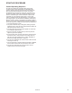
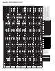
3. Loosen set screw on outer side of adjustable motor sheave
(see Figure 14.2).
4. To reduce the speed of the blower, turn outer side of motor
sheave counterclockwise.
5. To increase the speed of the blower, turn outer side of motor
sheave clockwise.
6. Retighten motor sheave set screw, replace belt and retighten
motor base. Adjust motor adjusting screw such that there
is 3/4" belt deflection when pressed with 5 pounds of force
midway between the blower and motor sheaves (see Figure
14.3). Since the belt tension will decrease dramatically
after an initial run-in period, it is necessary to periodically
re-check the tension to assure proper belt adjustment.
7. Check to make certain motor sheave and blower sheave are
aligned. Re-align if necessary.
8. Re-check blower speed after adjustment.
9. Check motor amps. Do not exceed amps shown on motor
nameplate. Slow blower if necessary.
10. Check air temperature rise across unit. Check temperature
rise against values shown in Performance Tables on page
20 to assure actual desired air flow is being achieved.
11. If adjustments are required, recheck motor amps after final
blower speed adjustment.
rpm (see performance table for units with or without blower
enclosure, page 20). See “Blower Adjustments” for setting of
drive pulley turns open.
If a blower unit is to be used with ductwork or nozzles, etc., the
total external static pressure under which the unit is to operate,
and the required air flow must be known before the unit can be
properly adjusted. Any device added externally to the unit, and
which the air must pass through, causes a resistance to air flow
called pressure loss.
If Modine filters are used, the pressure loss through the filters
is included in the performance data on page 20. If Modine
supplied discharge nozzles are used, the pressure drop of
the nozzles can be found footnoted at the bottom of page
23. If filters, nozzles or ductwork are to be used with the unit,
and they are not supplied by Modine, the design engineer
or installing contractor must determine the pressure loss for
the externally added devices or ductwork to arrive at the total
external static pressure under which the unit is to operate.
Once the total static pressure and the required air flow are
known, the operating speed of the blower can be determined
and the correct motor sheave adjustments made. As an
example, a model BDP350 is to be used with a Modine supplied
blower enclosure and filters attached to ductwork by others.
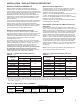
The unit is to move 6481 cfm of air flow against an external
static pressure of 0.2" W.C, which must be added for the filter
pressure drop for a total of 0.4" W.C. total pressure drop. The
performance table on page 20 for a BDP350, at 6481 cfm and
0.4" W.C. static pressure, shows that the unit will require a 5 hp
motor using a -207 drive, and the motor sheave should be set
at .5 turns open to achieve a blower speed of 1050 rpm.
To Install
1. Remove and discard the motor tie down strap and the
shipping block beneath the belt tension adjusting screw
(Not used on all models.)
2. For 3 and 5 HP motors, affix sheave to the motor shaft and
install motor on the motor mounting bracket. Install belt on
blower and motor sheaves.
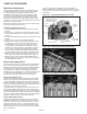
INSTALLATION
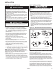
Figure 14.1 - Blower Model
THREADED MOUNTING BRACKETS ON
BLOWER ASSEMBLY
MOTOR SHEAVE
(MOVEABLE
FACE TO
OUTSIDE)
BLOWER
HOUSING
MOTOR
ADJUSTMENT
SCREW
MOTOR MOUNTING
BRACKET
BLOWER
SHEAVE
TOWARD MOTOR
SET SCREW
ADJUSTABLE HALF
OF SHEAVE
3/4" DEFLECTION
WITH 5# FORCE
Figure 14.2 -
Motor Sheave Adjustment
Figure 14.3 -
Belt Tension Adjustment