
Installation and Service Manual

25
6-580.12
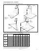
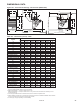
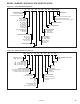
DIMENSIONAL DATA
W
X
F
C
G
DD
J
M (APPROX.)
L (MIN. DISTANCE TO WALL)
N
S
O
K
EE
5
DD
J
P
Q x V
R x T
/
8
"
7
4
/
16
"
9
5
/
4
"
3
/
16
"
9
FILTER RACK
(OPTIONAL)
BLOWER
ENCLOSURE
(OPTIONAL)
A
H
D (OPENING)
BB
E
AA
B
K
L (MIN. DISTANCE TO WALL)
G
➀
Vent connection is 5", connected to a factory supplied vent transition. For model sizes 150 and 175, the factory supplied
transition is 4" (to the power exhauster outlet) to 5" (to the vent system). For model size 200, the factory supplied transition
is 6" (to the power exhauster outlet) to 5" (to the vent system).
➁
BDP 150 thru BDP 300 — 4 holes (2 on blower and 2 on unit).
BDP 350 and BDP 400 —-6 holes (2 on blower and 4 on unit). (Listed is the hole diameter and threads per inch to
accept threaded rod).
➂
This is an approximate dimension for standard motors, allow 3" for sheave and optional motors.
➃
Distance between mounting hole in unit casing and mounting hole on blower. On the BDP 350 and BDP 400, the distance
is from rear mounting hole in casing to the mounting hole on blower.
➄
For natural gas; may vary depending on control availability.
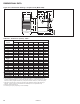
Dimension
Model Number
Symbol
BDP 150 BDP 175 BDP 200 BDP 250 BDP 300 BDP 350 BDP 400
A 21 23-1/2 25-5/8 25-5/8 28-5/8 33-5/8 40
B 35-1/4 35-1/4 40-1/4 40-1/4 40-1/4 40-1/4 40-1/4
C 22 22 25 25 25 25 25
D 18-9/16 21-1/16 23-3/16 23-3/16 26-3/16 31-3/16 37-1/2
E 20 20 24 24 24 24 24
F 12 12 13-1/2 13-1/2 14 – –
G 6-9/16 6-9/16 7-1/2 7-1/2 7-1/2 7-1/2 7-1/2
H 17-3/8 19-7/8 22 22 25 30 36-3/8
J 5 ➀ 5 ➀ 5 ➀ 6 6 6 6
K Mounting Holes ➁ 3/8-16 3/8-16 3/8-16 3/8-16 3/8-16 3/8-16 3/8-16
L w/ Blwr Encl & Filt Rk 62-5/8 62-5/8 69-5/8 69-5/8 69-5/8 69-5/8 69-5/8
L w/o Blwr Encl & Filt Rk 53-1/8 53-1/8 61 61 61 61 65
M ➂ 47-1/8 47-1/8 55 55 55 55 59
N ➃ 21-1/2 21-1/2 25-7/16 25-7/16 24-15/16 17-15/16 22
O 7-1/4 7-1/4 8-1/2 8-1/2 8-1/2 8-1/2 8-1/2
P 30 30 34 34 34 34 34
Q Blower Encl Ht 21-3/8 21-3/8 25-1/8 25-1/8 25-1/8 25-1/8 25-1/8
R Inlet Duct Height 20 20 23-3/4 23-3/4 23-3/4 23-3/4 23-3/4
S Center to Center
Blower Mtg. Holes
T Inlet Duct Width 27-1/2 27-1/2 32-3/4 32-3/4 32-3/4 42-7/8 42-7/8
V Blower Encl Width 29 29 34-1/4 34-1/4 34-1/4 44-3/8 44-3/8
W – – – – – 5 5
X – – – – – 16 16
AA 8 8 9 9 9 9 9
BB 7-1/4 7-1/4 7-1/4 7-1/4 7-1/4 7-1/4 7-1/4
DD 2-3/4 2-3/4 2-3/4 3-3/8 3-3/8 3-3/8 6-13/16
EE 56-5/8 56-5/8 63-5/8 63-5/8 63-5/8 63-5/8 63-5/8
Gas Connections ➄ 1/2 1/2 1/2 3/4 3/4 3/4 3/4
Blower Wheel Diameter 13 13 15 15 15 15 15
Approx. Weight 152 152 315 315 339 428 498
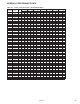
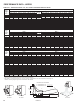
Figure 25.1 - Dimensional Drawings - Blower Units (Model BDP)
17-5/16 17-3/8 20-3/8 20-3/8 20-3/8 20-3/8 20-3/8
Table 25.1 - Dimensions (inches) - BDP