
Installation and Service Manual

24
6-580.12
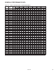
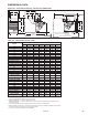
DIMENSIONAL DATA
Dimension Model Number
Symbol PDP 150 PDP 175 PDP 200 PDP 250 PDP 300 PDP 350 PDP 400
A 21 23-1/2 25-5/8 25-5/8 28-5/8 33-5/8 40
B 35-1/4 35-1/4 40-1/4 40-1/4 40-1/4 40-1/4 40-1/4
C 22 22 25 25 25 25 25
D 18-9/16 21-1/16 23-3/16 23-3/16 26-3/16 31-3/16 37-1/2
E 20 20 24 24 24 24 24
F 12 12 13-1/2 13-1/2 14 – –
G 6-9/16 6-9/16 7-1/2 7-1/2 7-1/2 7-1/2 7-1/2
H 17-3/8 19-7/8 22 22 25 30 36-3/8
J 5 ➁ 5 ➁ 5 ➁ 6 6 6 6
K (Mounting
Holes)
➂
L
➃ 35-13/16 35-9/16 40-3/4 40-3/4 40-3/4 40-3/4 44-3/16
M 29-13/16 29-9/16 34-3/4 34-3/4 34-3/4 34-11/16 38-3/16
W – – – – – 5 5
X – – – – – 16 16
AA 8 8 9 9 9 9 9
BB 7-1/4 7-1/4 7-1/4 7-1/4 7-1/4 7-1/4 7-1/4
DD 2-3/4 2-3/4 3-3/8 3-3/8 3-3/8 3-3/8 6-13/16
EE 30-1/2 30-1/2 32-7/8 32-7/8 32-7/8 32-7/8 32-7/8
LL 31-1/8 31-1/8 34-7/8 34-7/8 36-1/4 35-1/2 40-1/2
Gas Connections
➄
1/2 1/2 1/2 3/4 3/4 3/4 3/4
Fan Diameter 16 18 20 20 22 22 24
Approx. Weight 168 175 239 239 269 338 418
➀ Do not use propeller units with duct work.
➁ Vent connection is 5", connected to a factory supplied vent transition. For model sizes 150 and 175,
the factory supplied transition is 4" (to the power exhauster outlet) to 5" (to the vent system). For model
size 200, the factory supplied transition is 6" (to the power exhauster outlet) to 5" (to the vent system).
➂ PDP 150 through PDP 300 - 2 holes (and the level hanging adjustment feature). PDP 350 through
PDP 400 - 4 holes. (Listed is the hole diameter and threads per inch to accept threaded rod).
➃ Dimension equals overall plus 6".
➄ For natural gas; may vary depending on control availability.
Table 24.1 - Dimensions (inches) - PDP ➀
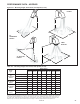
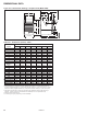
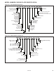
Figure 24.1 - Dimensional Drawings - Propeller Units (Model PDP)
A
H
D (OPENING)
BB
E
AA
B
K
W
X
F
C
M
EE
LL
G
DD
J
L
(MIN. DISTANCE TO WALL)
K
3/8-16 3/8-16 3/8-16 3/8-16 3/8-16 3/8-16 3/8-16